5 Temperature Measurement Module DVP04TC-E2
1. Conn
ectio
n
port for extension unit/module 6. Terminals
2. DIN rail (35mm) 7. Mounting hole
3. Model name 8. Fixing clip for extension unit/module
4. POWER, ERROR, AD indicators 9. Mounting port for extension unit/module
5. DIN rail clip
I/O terminals
+
I1 FEI1 FEI2I2
+
FE I4
+
I4
0V24V FE FEFE FE FE
FEI3
+
I3
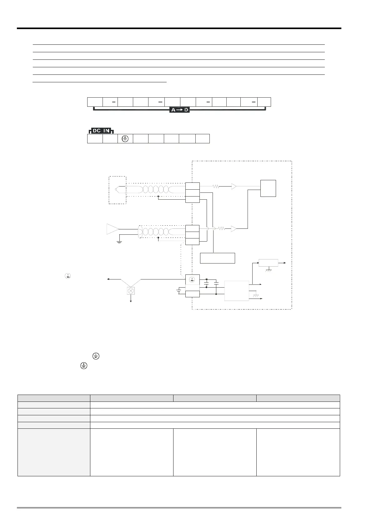
5.4 External Wiring
CH1
CH4
DC/ DC
5V
AG
+15V
-15V
AG
24V
0V
FE
I1 -
I1+
*2
*3
+
-
100
MUX
FE
I4 -
I4+
Thermocouple
-80mV~80mV
Shielded
cable *1
Shielded
cable *1
Cold-Junction
Compensation
Converter
System
grounding
Terminal of
power module
Ea rth
(100 or less)Ω
Voltag e input
*1: Wiring for analog input should adopt the connection cable or shielding cable of thermocouple temperature
sensor J-type, K-type, R-type, S-type, T-type, E-type and N-type and should be separated from other
power cable or wirings that may cause interference.
*2: Connect FE with
terminal for noise suppression..
*3: Connect the
terminal on both power module and DVP04TC-E2 to the system grounding point then
ground the point or connect it to the cover of power distribution cabinet.
5.5 Functions and Specifications
DVP04TC-E2 Celsius (°C) Fahrenheit (°F) Voltage input
Power supply voltage 24V DC (20.4V DC ~ 28.8V DC) (-15% ~ +20%)
Connector European standard fixed terminal block (Pin pitch: 5mm)
Analog input channel 4 channels
Applicable sensor types J-type, K-type, R-type, S-type, T-type, E-type, N-type thermocouple; ±80mV input impedance
Range of input
J-type: -100°C ~1,150°C
K-type: -100°C ~ 1,350°C
R-type: 0°C ~ 1,750°C
S-type: 0°C ~ 1,750°C
T-type: -150°C ~ 390°C
E-type: -150°C ~ 980°C
N-type: -150°C ~ 1,280°C
J-type: -148°F ~ 2,102°F
K-type: -148°F ~ 2,642°F
R-type: °F ~ 3,182°F
S-type: °F ~ 3,182°F
T-type: -238°F ~734°F
E-type: -238°F ~ 1,796°F
N-type: -238°F ~2336°F
±80mV
DVP-ES2 Module Manual
-2

 Loading...


