5 Temperature Measurement Module DVP04TC-E2
CR#128, 148, 168, 188: Heating/cooling
[Explanation]
Select heating or cooling control. Set the CR to “0” if your control target is a heater. Set the CR to “1” if your
control target is a cooler. The default setting = H’0000.
Mode 0 (H’0000): Heater.
Mode 1 (H’0001): Cooler.
CR#129, 149, 169, 189: Upper limit of output. Default = K32,000
CR#130, 150, 170, 190: Lower limit of output. Default = K0
[Explanation]
1. The output volume is calculated from the upper limit and lower limit.
2. For example, if the upper/lower limit is set to 0 ~ 32,000, when the output comes to 50%, the output
volume will be 16,000. Please set up this CR according to the analog output you are using.
CR#131, 151, 171, 191: Output percentage (0.1%)
[Explanation]
The result obtained from the PID operation. Unit: 0.1%. For example, if the PID operating result is 100, the
output percentage will be 10%.
CR#132, 152, 172, 192: Output width (ms)
CR#133, 153, 173, 193: Output cycle (ms)
[Explanation]
If you are using the cyclic control mode to control your target, please read the two CRs. For example, if the
cycle is 2,000 and width 1,000, the output pulse will shape like below:
Output Y0
t=1000ms
T=2000ms
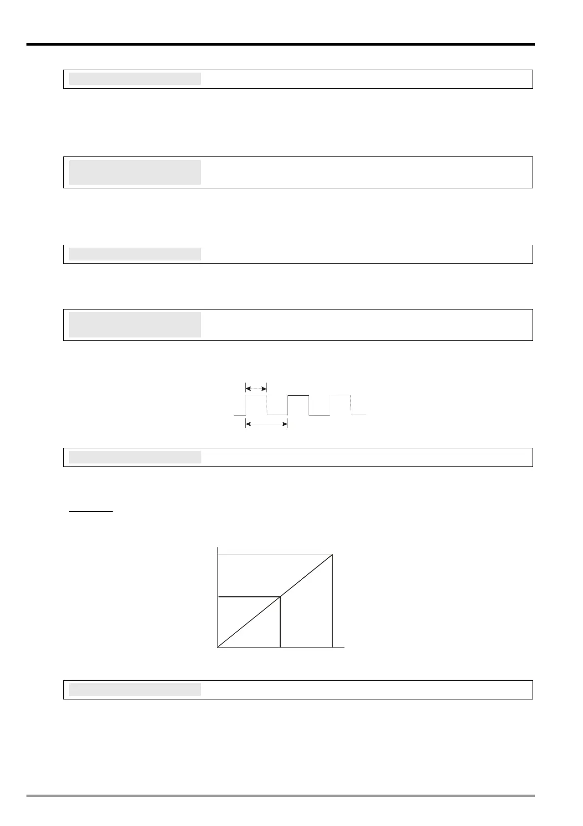
CR#134, 154, 174, 194: Output volume
[Explanation]
Formula of output volume:
Output Volume = (Output Upper Limit – Output Lower Limit) × Output % + Output Lower Limit
Example:
Control by current 4 ~ 20mA (0 ~ 32,000)
Output upper limit: 32,000
Output lower limit: 0
32000
(100%)
16000
(50%)
0 (0%)
4mA
12mA
20mA
Output volume
Output
current
CR#135, 155, 175, 195: PID_RUN/STOP
[Explanation]
1. If you want to apply auto-tuning function, enable auto-tuning function before setting PID function as
RUN. When auto-tuning is completed, CR#136, 156 , 176, 196 will be cl ear ed as 0, an d th e
obtained value of K
P
/ K
I
/ K
D
will be stored into corresponding CRs.
2. PID_RUN/STOP, K0: STOP, K1: RUN. Default = K0.
DVP-ES2 Module Manual
-10

 Loading...


