DVP-ES2/EX2/EC5/SS2/SA2/SX2/SE&TP Operation Manual - Programming
Program example 5: COM2(RS-485), Function Code H05
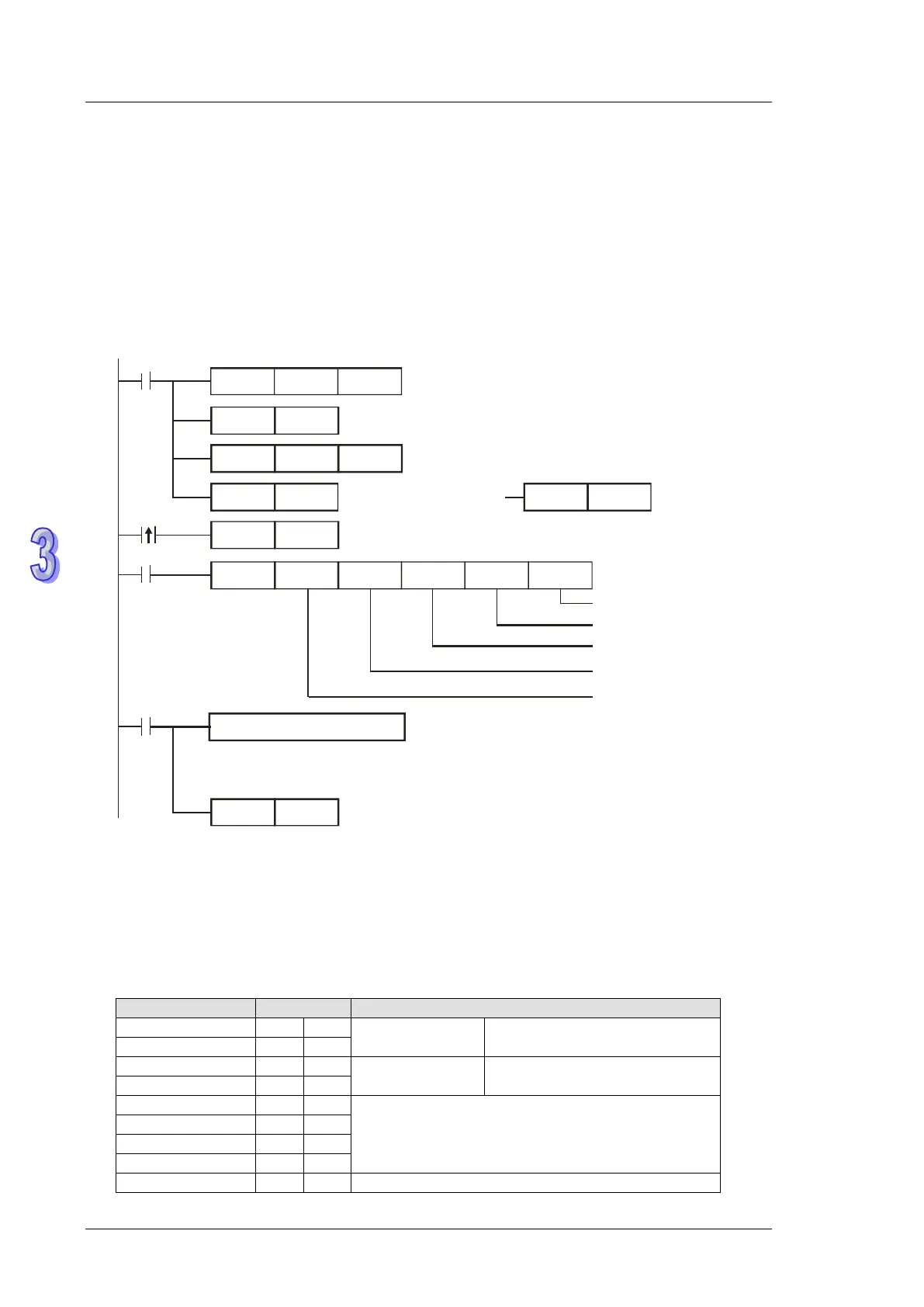
1. Function code K5(H05): Force ON/OFF bit device
2. PLC1 connects to PLC2: (M1143 = OFF, ASCII mode), (M1143 = ON, RTU Mode)
3. n = 1 indicates Force ON (set FF00H) and n = 0 indicates Force OFF (set 0000H)
4. For ASCII or RTU mode, PLC COM2 stores the data to be sent in D1256~D1295 and stores the
received data in D1070~D1085
5. Take the connection between PLC1 (PLC COM2) and PLC2 (PLC COM1) for example, the
tables below explain the status when PLC1 Force ON PLC2 Y0.
H87
MOV
M1002
D1120
SET
M1120
K100
MOV
D1129
RST
M1127
MODRW
K5
K1
X0
H0500 D0
K1
Function Code K5:
Force ON/OFF bit device
Reserved
Force ON status (Set FF00H)
M1127
SET
X0
M1122
RST
M1143
SET
M1143
Connection device address: K1
Da ta a ddres s : Y0 = H0500
M1143 = OFF
ASCII mode
Reset M1127
Set communication protocol as 9600,8,E,1
Re ta in communica tion protoc ol
Set receiving timeout as 100ms
ASCII mode: The received data is stored in D1070~D1085 in ASCII format
RTU mode: The received data is stored in D1070~D1085 in Hex.
Sending request
Processing received data
M1143 = ON
RTU mode
Re ceiving co mp le te d
ASCII mode (M1143 = OFF):
When X0 = ON, MODRW instruction executes the function specified by Function Code 05
PLC1 PLC2, PLC sends: “01 05 0500 FF00 6F”
PLC2 PLC1, PLC receives: “01 05 0500 FF00 6F”
Registers for data to be sent (sending messages)
Device address: ADR (1,0)
CMD (1,0) Control parameter
Data Address
High byte to be force ON/OFF