DVP-ES2/EX2/EC5/SS2/SA2/SX2/SE&TP Operation Manual - Programming
7.2.2 The Profile
7.2.3 The CAN Interface and the Network Topology
The pins of COM3 (CAN interface)
Pin Description
White (CAN_H)
Blue (CAN_L)
D+
D-
CAN+
SG
CAN-
Black(SG)
CAN+ CAN-H
CAN- CAN-L
SG
Signal
ground
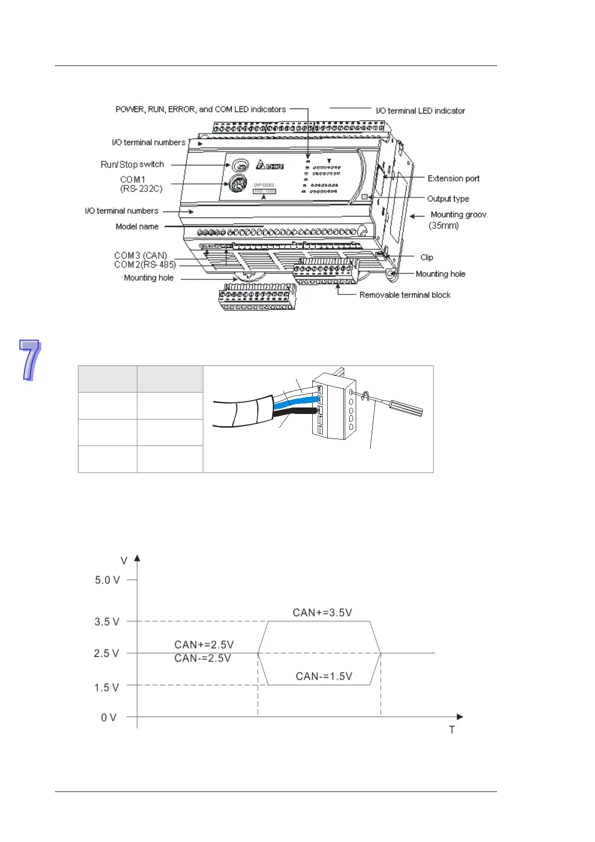
The CAN signal and the data frame format
The CAN signal is a differential signal. The voltage of the signal is the voltage difference between
CAN+ and CAN-. The voltage of CAN+ and that of CAN- take SG as a reference point. The CAN
network can be in two states. One is a dominant level, and is indicated by the logical “0”. The other
is a recessive level, and is indicated by the logical “1”. The CAN signal level is shown below.
Tighten it with a slotted
screwdriver.