DVP-ES2/EX2/EC5/SS2/SA2/SX2/SE&TP Operation Manual - Programming
Points to note: (Used with Mitsubishi MR-J2 Servo drive)
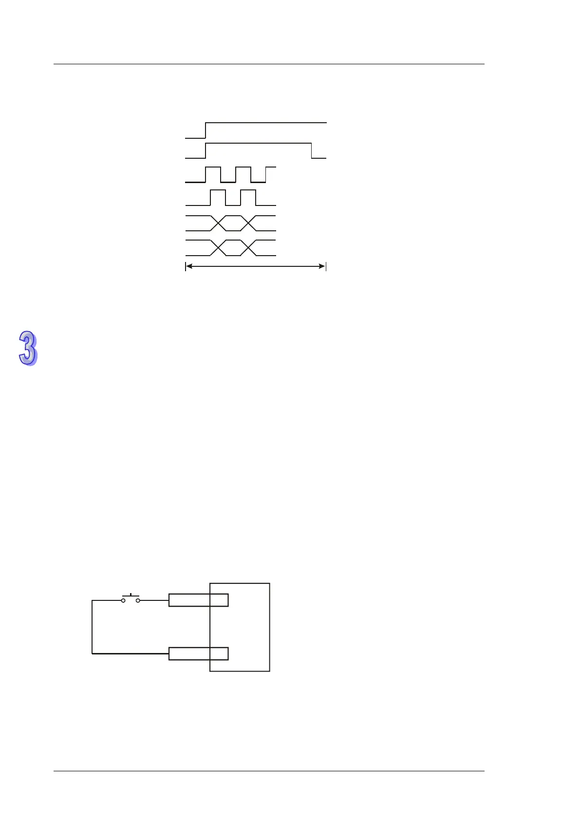
1. Timing diagram of the operation of DABSR instruction:
SON
ABSM
TLC
ABSR
ZSP
D01
AMP output
Servo ON
ABS(bit 1)
ABS(bit 0)
ABS request
Transmission ready
ABS data
mode
transmission
Current position data 32-bit
+ check data 6-bit
Controller output
AMP output
AMP output
2. When DABSR instruction executes, servo ON (SON) and ABS data transmission mode are
driven for output.
3. By “transmission ready” and “ABS request” signals, users can confirm the transmitting and
receiving status of both sides as well as processing the transmission of the 32-bit ABS position
data and the 6-bit check data..
4. Data is transmitted by ABS (bit0, bit1).
5. This instruction is applicable for servo drive with absolute position check function, e.g.
MITSUBISHI MR-J2-A.
6. Select one of the following methods for the initial ABSR instruction:
Execute API 156 ZRN instruction with reset function to complete zero return.
Apply JOG function or manual adjustment to complete zero return, then input the reset
signal to the servo. Please refer to the diagram below for the wiring method of reset signal.
For the detailed wiring between DVP-PLC and Mitsubishi MR-J2-A, please refer to API 159
DRVA instruction.
CR 8
SG 10
reset
Ex: Mitsubishi MR-J2-A