Communication Module DVPSCM12/52-SL
DVP-PLC Operation Manual
10
CR#8: Reference address of the data sent through COM2 in UD Link
[Description]
Please refer to the description of
CR#4.
CR#9: Reference address of the data received through COM2 in UD Link
[Description]
Please refer to the description of
CR#5.
CR#10: Module status
[Description]
The PLC controls RUN/STOP status of the SCM module.
CR#11~19: Error flag
[Description]
With regard to the error flag in the SCM module, please refer to chapter 8.
CR#20~27:UD Link status
[Description]
The execution status of UD Link
CR#30: Triggering the UD Link sequence
[Description]
High byte: COM1; Low byte: COM2
Enter directly the number of times the UD Link sequence is triggered.
0: Not triggered; 1~254: Number of times he UD Link sequence is triggered; 255 (H' FF): Always triggered
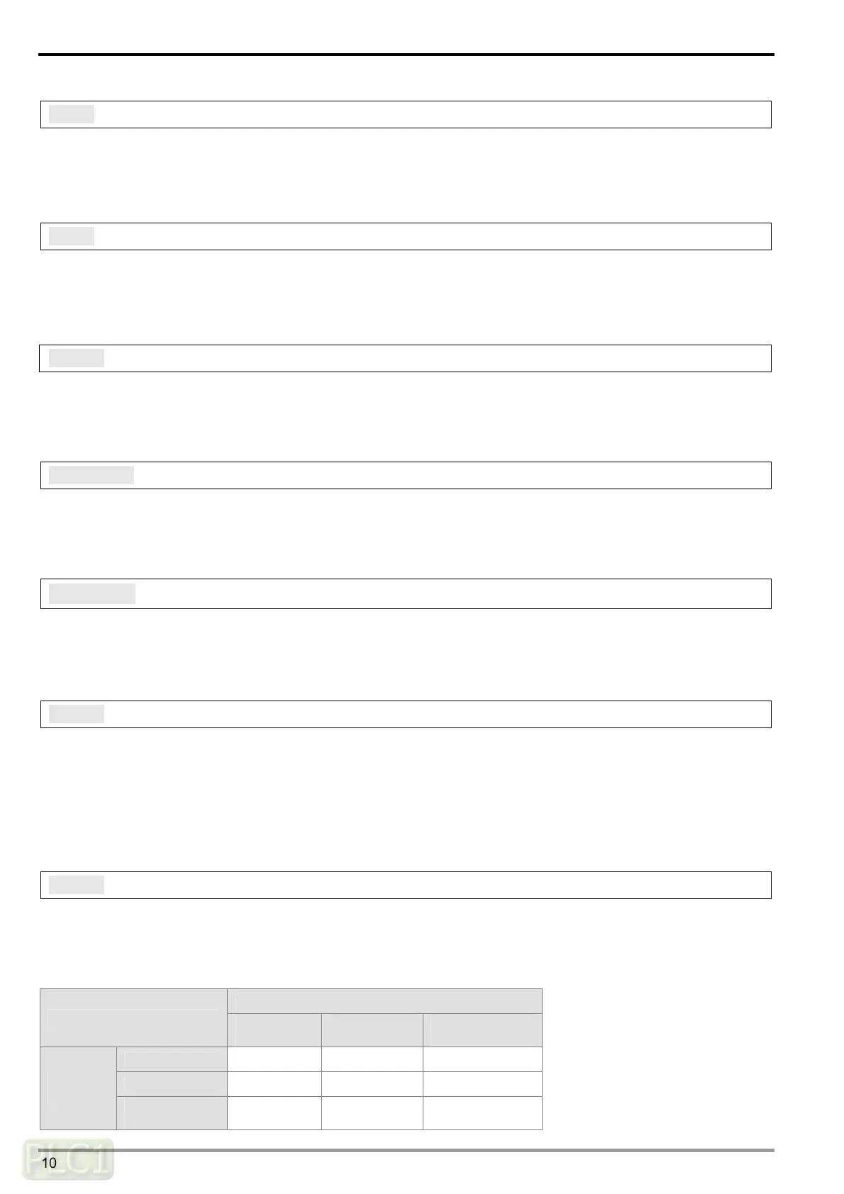
CR#31: Triggering the data exchange through COM1 to read bits or words
[Description]
High byte: COM1 Bit; Low byte: COM1 Word
0: Not triggered; 1: Triggered once; 2: Always triggered
COM1 Word
Not
triggered
Triggered
once
Always
triggered
Not triggered
H' 0000 H' 0001 H' 0002
Trigger once
H' 0100 H' 0101 H' 0102
COM1
Bit
Always
triggered
H' 0200 H' 0201 H' 0202
 Loading...