RMC70 Startup Guide
40 Delta Computer Systems, Inc.
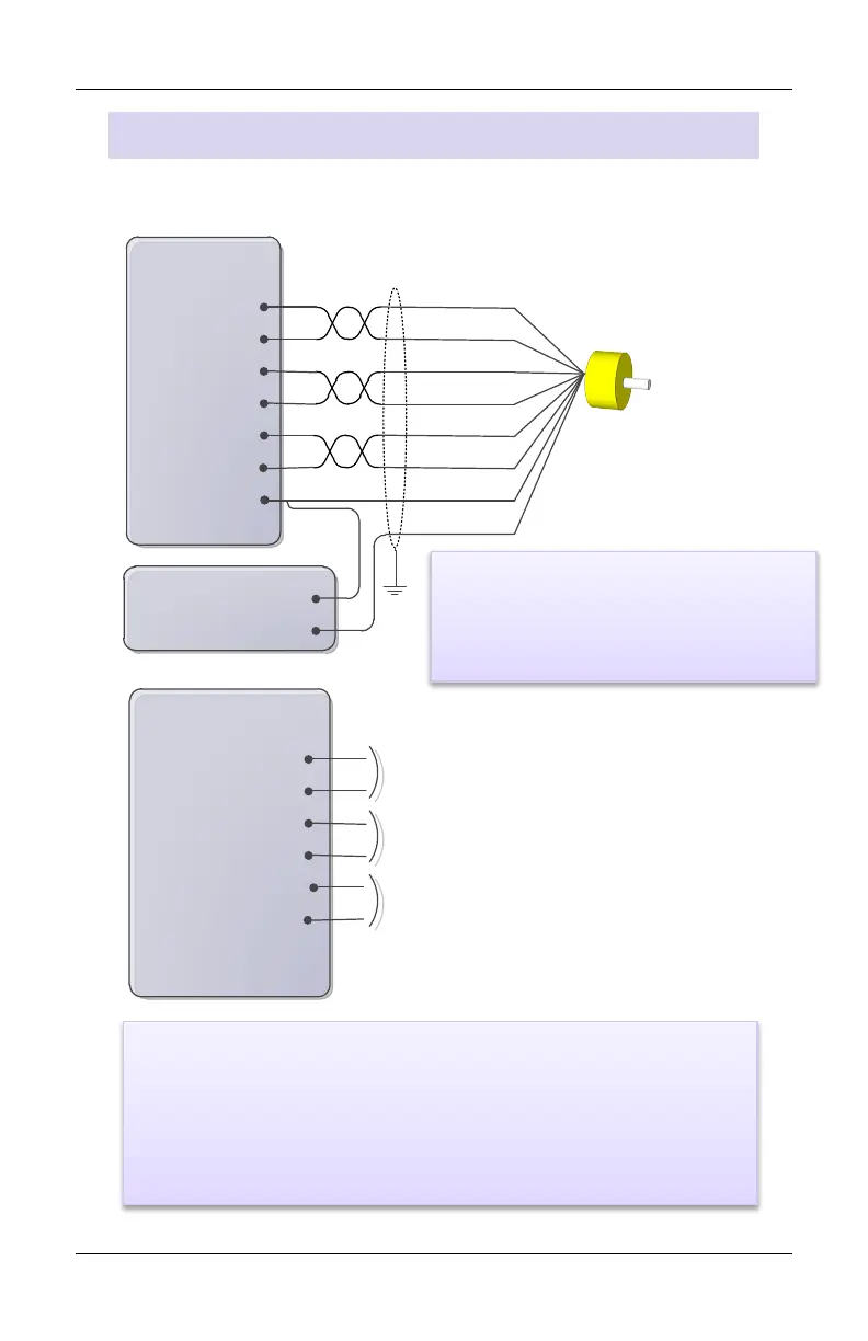
25-pin Axis
Connector
A-
A+
B+
Z-
Power Supply
+Pwr
Cmn
Pin 1: A-
Pin 2: A+
Pin 3: B-
Pin 4: B+
Pin 14: Z-
Cmn
Z+
B-
Pin 15: Z+
25-pin Axis
Connector
Pin 6: RegY/NegLim-
Pin 7: RegY/NegLim+
Pin 8: RegX/PosLim-
Pin 9: RegX/PosLim+
Pin 18: Home-
Pin 19: Home+
Pwr+
Common
Apply 12-24 VDC across input to turn on
Apply 12-24 VDC across input to turn on
Apply 12-24 VDC across input to turn on
QA Module Wiring
See page 41 for the QA module pin-out.
The A, B and Z signals accept
5 V differential (RS-422) signals only!
• Compatible with 12-24 VDC.
• Max current draw is 2.7 mA max.
• Turn on when the voltage is greater than 6 V. The polarity is
unimportant.



 To Next Page