Amplon RT Series
16
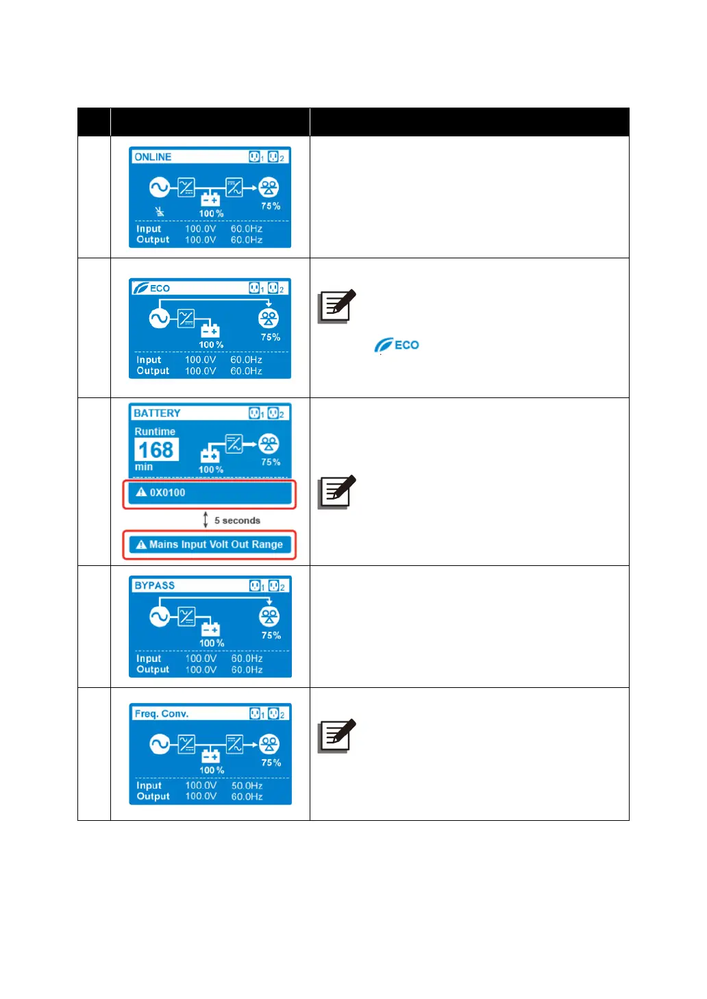
3.3.2 Operation Mode Diagram Definition
No.
Diagram Description
1
Indicates
ONLINE
mode.
2
Indicates ECO mode.
NOTE:
In
ECO
mode, the power flow diagram
will change according to the UPS’s input
voltage and frequency. However, the icon
shown in the upper-left corner will
not change even if the UPS transfers to online
mode or battery mode.
3
Indicates BATTERY mode.
NOTE: The error code and the alarm
message will appear alternatively for every 5
seconds.
4
Indicates BYPASS mode.
5
Indicates Frequency Conversion mode.
NOTE:
In Frequency Conversion mode, the power
flow diagram will change according to the
UPS’s input voltage and frequency. However,
the icon Freq. Conv. shown in the upper-left
corner will not change even if the UPS
transfers to battery mode.