Chapter 12 Description of Parameter Settings|CFP2000 Series
12.1-02-13
Settings Functions Descriptions
32
△-connection for the
Motor Coil
Active when PR.05-24=1, when frequency output is higher than
Pr.05-23 plus 2Hz, continues longer than 05-25.
33
Zero Speed (actual
output frequency)
Active when the actual output frequency is 0. (the drive should be
at RUN mode)
34
Zero Speed with Stop
(actual output frequency)
Active when the actual output frequency is 0 or Stop.
35
Error Output Selection 1
(Pr.06-23)
Active when Pr.06-23 is ON.
36
Error Output Selection 2
(Pr.06-24)
Active when Pr.06-24 is ON.
37
Error Output Selection 3
(Pr.06-25)
Active when Pr.06-25 is ON.
38
Error Output Selection 4
(Pr.06-26)
Active when Pr.06-26 is ON.
39 Reserved
40
Speed Attained
(including zero speed)
Active when the output frequency reaches frequency setting or
stop.
41~43 Reserved
44 Low Current Output This function needs to be used with Pr.06-71 ~ Pr.06-73
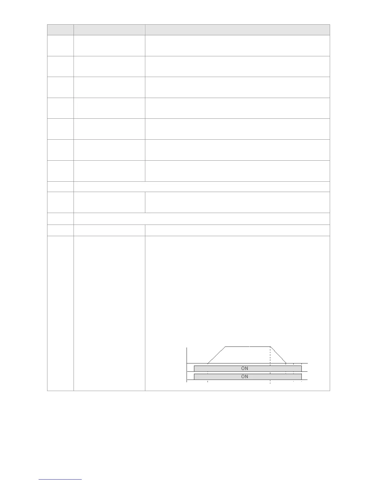
45
UVW Phase Magnet
Contractor ON/ OFF
Switch
1. Under FOCPG control mode, set MI=49 (drive enable) and
MO=45 (electromagnetic contractor ON/OFF switch), then the
magnetic contactor will follow the drive status to be ON or OFF.
2. For brake control, set MO=12 (mechanical brake release),
Pr.02-31=T1 sec (mechanical brake delay time); then
enable/disable DC braking by set 07-01 (DC brake current) to any
level except 0 and set Pr.07-02 = T2 (DC brake time at start up)
and Pr.07-03 = T2 (DC brake current at stop). It is recommend to
set T2 >T1 and try to activate brake control during zero-speed
status.
Enabl e
Contactor
 Loading...
