Chapter 12 Description of Parameter Settings|CFP2000 Series
12.1-02-14
Settings Functions Descriptions
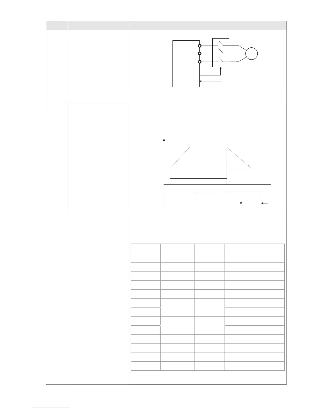
Motor
U(T1)
V(T2)
W(T3)
IM
3~
MC
MOx=45
MIx=49
AC Driver
46 Reserved
47 Brake Release at Stop
When drive stops, the corresponding multi-function terminal will
be ON if the frequency is less than Pr.02-34. After it is ON, it will
be OFF when brake delay time exceeds Pr.02-32.
Multi-function
Output
MO=d47
Output Frequenc
02-32
RUN
RUN
Time
Output Frequency
< Pr.02-34
48~49 Reserved
50
Output for CANopen
control
Control multi-function output terminals through CANopen.
If to control RY2, then the Pr02-14 = 50.
The mapping table of the CANopen DO is below:
physical
terminal
Setting of
related
parameters
Attribute
Corresponding Index
RY1 P2-13 = 50 RW The bit 0 at 2026-41
RY2 P2-14 = 50 RW The bit 1 at 2026-41
MO1 P2-16 = 50 RW The bit 2 at 2026-41
MO2 P2-17 = 50 RW The bit 3 at 2026-41
MO10
P2-36 = 50 RW
The bit 4 at 2026-41
RY10 The bit 5 at 2026-41
MO11
P2-37 = 50 RW
The bit 6 at 2026-41
RY11 The bit 7 at 2026-41
RY12 P2-38 = 50 RW The bit 8 at 2026-41
RY13 P2-39 = 50 RW The bit 9 at 2026-41
RY14 P2-40 = 50 RW The bit 10 at 2026-41
RY15 P2-41= 50 RW The bit 0 at 2026-41
Refer to Chapter 15-3-5 for more information.
 Loading...
