Chapter 12 Description of Parameter Settings|CFP2000 Series
12.1-02-15
Settings Functions Descriptions
51 Output for RS-485
For RS485 output.
52
Output for
communication card
For communication output of communication cards
(CMC-MOD01, CMC-EIP01, CMC-PN01 and CMC-DN01)
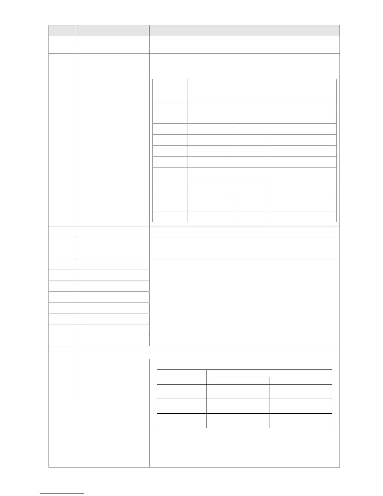
Physical
terminal
Setting of
related
parameters
Attribute
Corresponding
Address
RY1 P2-13 = 51 RW The Bit 0 of 2640
RY2 P2-14 = 51 RW The Bit 1 of 2640
P2-15 = 51 RW The Bit 2 of 2640
MO1 P2-16 = 51 RW The Bit 3 of 2640
MO2 P2-17 = 51 RW The Bit 4 of 2640
MO3 P2-18 = 51 RW The Bit 5 of 2640
MO4 P2-19 = 51 RW The Bit 6 of 2640
MO5 P2-20 = 51 RW The Bit 7 of 2640
MO6 P2-21 = 51 RW The Bit 8 of 2640
MO7 P2-22 = 51 RW The Bit 9 of 2640
MO8 P2-23 = 51 RW The Bit 10 of 2640
53 Fire mode indication
When #58 or #59 is enabled, this function will work.
54
By pass fire mode
indication
When bypass function is enabled in the fire mode, this contact will
work.
55 Motor #1 output
When setting multi-motor circulative function, the multi-function
output terminal will automatically set up Pr02-13~Pr02-15 and
Pr02-36~Pr02-40 in accordance with Pr12-01’s setting.
56 Motor #2 output
57 Motor #3 output
58 Motor #4 output
59 Motor #5 output
60 Motor #6 output
61 Motor #7 output
62 Motor #8 output
63~65 Reserved
66 SO contact A (N.O.)
Status of drive
Status of safety output
N.O. (MO=66) N.C. (MO=68)
Normal
Broken circuit
(Open)
Short circuit
(Close)
STO
Short circuit
(Close)
Broken circuit
(Open)
STL1~STL3
Short circuit
(Close)
Broken circuit
(Open)
68 SO contact B (N.C.)
67
Analog input signal level
achieved
Multi-function output terminals operate when analog input signal
level is between high level and low level.
03-44: Select the analog signal channel, AVI, ACI, and AUI which
is going to be compared.
03-45: The high level of analog input, factory setting is 50%.
 Loading...
