Chapter 12 Description of Parameter Settings|CFP2000 Series
12.1-06-12
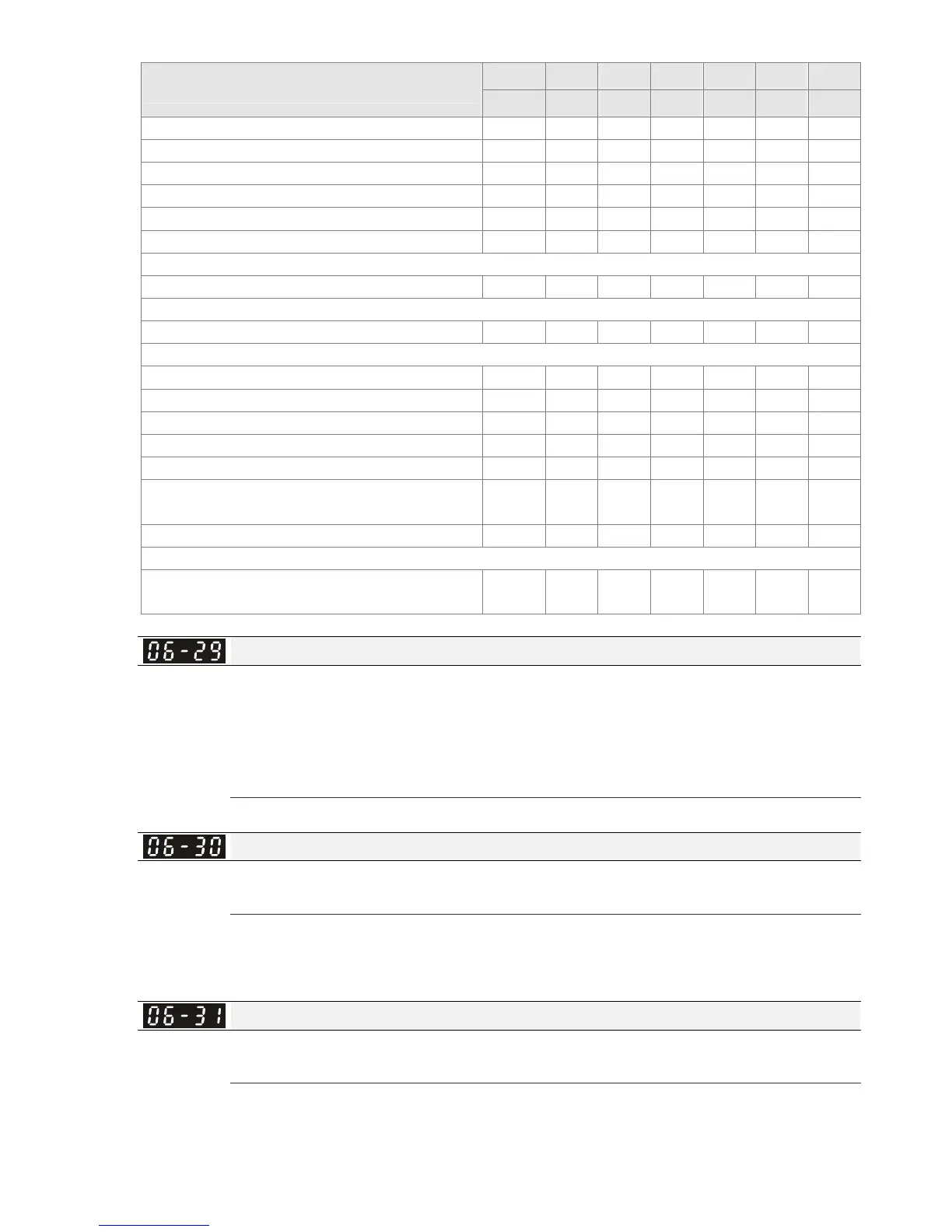
Fault Code
Bit0 Bit1 Bit2 Bit3 Bit4 Bit5 Bit6
current Volt. OL SYS FBK EXI CE
79: U phase over current (Uocc) ●
80: V phase over current (Vocc) ●
81: W phase over current (Wocc) ●
82: OPHL U phase output phase loss ●
83: OPHL Vphase output phase loss ●
84: OPHL Wphase output phase loss ●
85~89: Reserved
90: Inner PLC function is forced to stop
91~98: Reserved
99: TRAP CPU command error ●
100: Reserved
101: CGdE CANopen software disconnect1 ●
102: CHbE CANopen software disconnect2 ●
103: CSyE CANopen synchronous error ●
104: CbFE CANopen hardware disconnect ●
105: CIdE CANopen index setting error ●
106: CAdE CANopen slave station number
setting error
●
107: CFrE CANopen index setting exceed limit ●
108~110: Reserved
111: InrCOM Internal communication overtime
error
●
PTC (Positive Temperature Coefficient) Detection Selection
Factory Setting: 0
Settings 0: Warn and keep operating
1: Warn and ramp to stop
2: Warn and coast to stop
3: No warning
Pr.06-29 setting defines how the will drive operate after PTC detection.
PTC Level
Factory Setting: 50.0
Settings 0.0~100.0%
It needs to set AVI1/ACI/AVI2 analog input function Pr.03-00~03-02 to 6 (P.T.C. thermistor input
value).
It is used to set the PTC level, and the corresponding value for 100% is max. analog input value.
Frequency Command for Malfunction
Factory Setting: Read only
Settings 0.00~655.35Hz
When malfunction occurs, use can check the frequency command. If it happens again, it will
overwrite the previous record.
 Loading...
