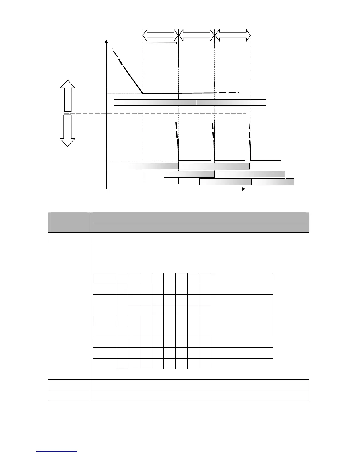
time
freq
P12-05 P12-05
Pump #2 on AC Mains Pump #2 off
Pump #3 on AC Mains Pump #3 off
Diagram 12-10: Sequence of switching motors at fixed quantity control with PID – Decreasing Demand
Parameter
Setting
Description
P12-00=3 Choose Fixed quantity control
P12-01=X
Number of Motors: Maximum 8 motors. After setting number of motor to be connected at
the same time, multi-function output terminals will follow automatically the setting as
shown in the table below.
P12-01 01 02 03 04 05 06 07 08
P02-13 55 55 55 55 55 55 55 55 Motor #1 by Mains
P02-14 56 56 56 56 56 56 56 Motor #2 by Mains
P02-15 57 57 57 57 57 57 Motor #3 by Mains
P02-36 58 58 58 58 58 Motor #4 by Mains
P02-37 59 59 59 59 Motor #5 by Mains
P02-38 60 60 60 Motor #6 by Mains
P02-39 61 61 Motor #7 by Mains
P02-40 62 Motor #8 by Mains
Table 2: Setting of Multi-function Output Terminal on Circulating Motors
P12-05=X Delay time while fixed quantity circulation at Motor Switching (seconds)
P12-06=X Frequency when switching motors at fixed quantity circulation (Hz)
Disable Motor’s Output
Set the Multifunction Input Commands as Disable Motors’ Output can stop corresponding motors.
The settings are::