Chapter 6 Control TerminalsMS300 (High Speed Model)
6-3
Terminals Terminal Function Factory Setting (NPN mode)
+24V
Digital control signal common
(Source)
+24V ± 10 % 100 mA
MI1
~
MI7
Multi-function input 1~7
Refer to parameters 02-01~02-07 to program the
multi-function inputs MI1~MI7.
Source Mode
ON: the activation current is 3.3 mA ≥ 11 VDC
OFF: cut-off voltage ≤
5 VDC
Sink Mode
ON: the activation current is 3.3 mA ≤ 13 VDC
OFF: cut-off voltage ≥ 19 VDC
When Pr. 02-00=0, MI1 and MI2 can be programmed
When Pr. 02-00≠0, the function of MI1 and MI2 is acc.
to Pr. 02-00 setting.
When Pr. 02-07=0, MI7 is pulse input terminal.
MI7 uses pulse input, the maximum input frequency =
33 kHz, can be used as frequency command source
or connected to the encoder as motor closed loop
control.
MI7 motor closed loop control only supports VFPG
control mode.
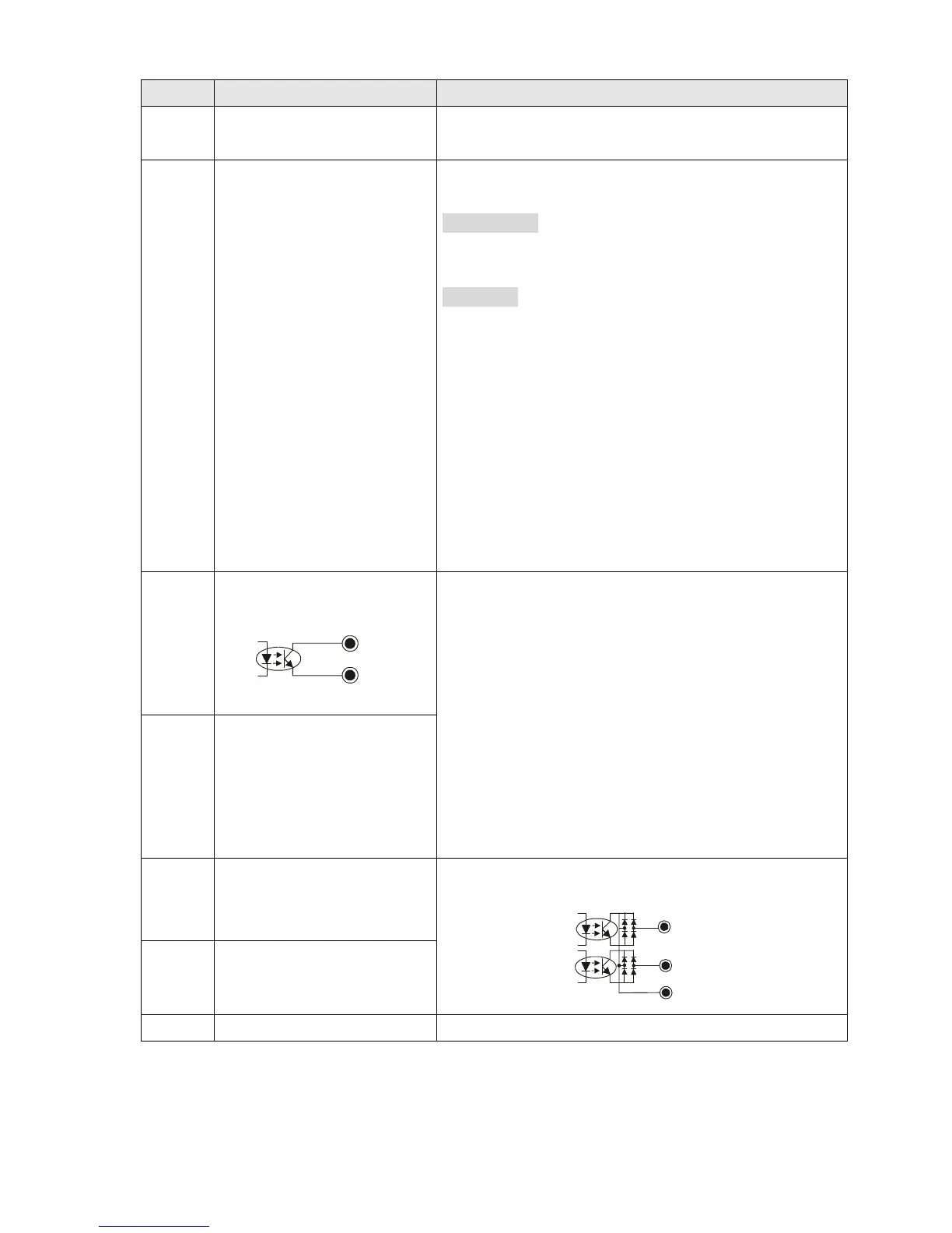
DFM
Digital frequency meter
DFM
DCM
DFM is a pulse-signal output; Duty-cycle: 50 %
Min. load impedance R
L
: 1 kΩ / 100 pf
Max. current: 30 mA
Max. capacitive load: 100 pF
Max. voltage: 30 VDC ± 1 %
(when 30 VDC / 30 mA /R
L
= 100 pf)
Max. output frequency: 33 kHz
Internal current limiting resistor R: ≥
1 KΩ
Output load impedance R
L
Capacitive load ≤ 100 pf
Resistive load ≥1 kΩ,resistance determine the output
voltage value.
DFM-DCM voltage = external voltage * ( R
L
/ (R
L
+R) )
DCM
Digital frequency signal
common (Sink)
MO1
Multi-function output 1
(photocoupler)
Programmable open-collector output, see Pr. 02-16 and
Pr. 02-17.
MO2
MCM
MO1
MO2
Multi-function output 2
(photocoupler)
MCM Multi-function output common Max 48 VDC 50 mA
 Loading...


