Chapter 6 Control TerminalsMS300 (High Speed Model)
6-4
Terminals Terminal Function Factory Setting (NPN mode)
RA
Multi-function relay output 1
(Relay N.O. a)
Programmable relay output, see P
. 02-13.
Resistive Load
3 A (N.O.) / 3 A (N.C.) 250 VAC
5 A (N.O.) / 3 A (N.C.) 30 VDC
Inductive Load (COS 0.4)
1.2 A (N.O.)/ 1.2 A (N.C.) 250 VAC
2.0 A (N.O.)/ 1.2 A (N.C.) 30 VDC
Various kinds of monitor signals output, e.g.: operation,
frequency attained, overload indication etc..
RB
Multi-function relay output 1
(Relay N.C. b)
RC
Multi-function relay common
(Relay)
+10V Potentiometer power supply
+10.5 ± 0.5 VDC / 20 mA
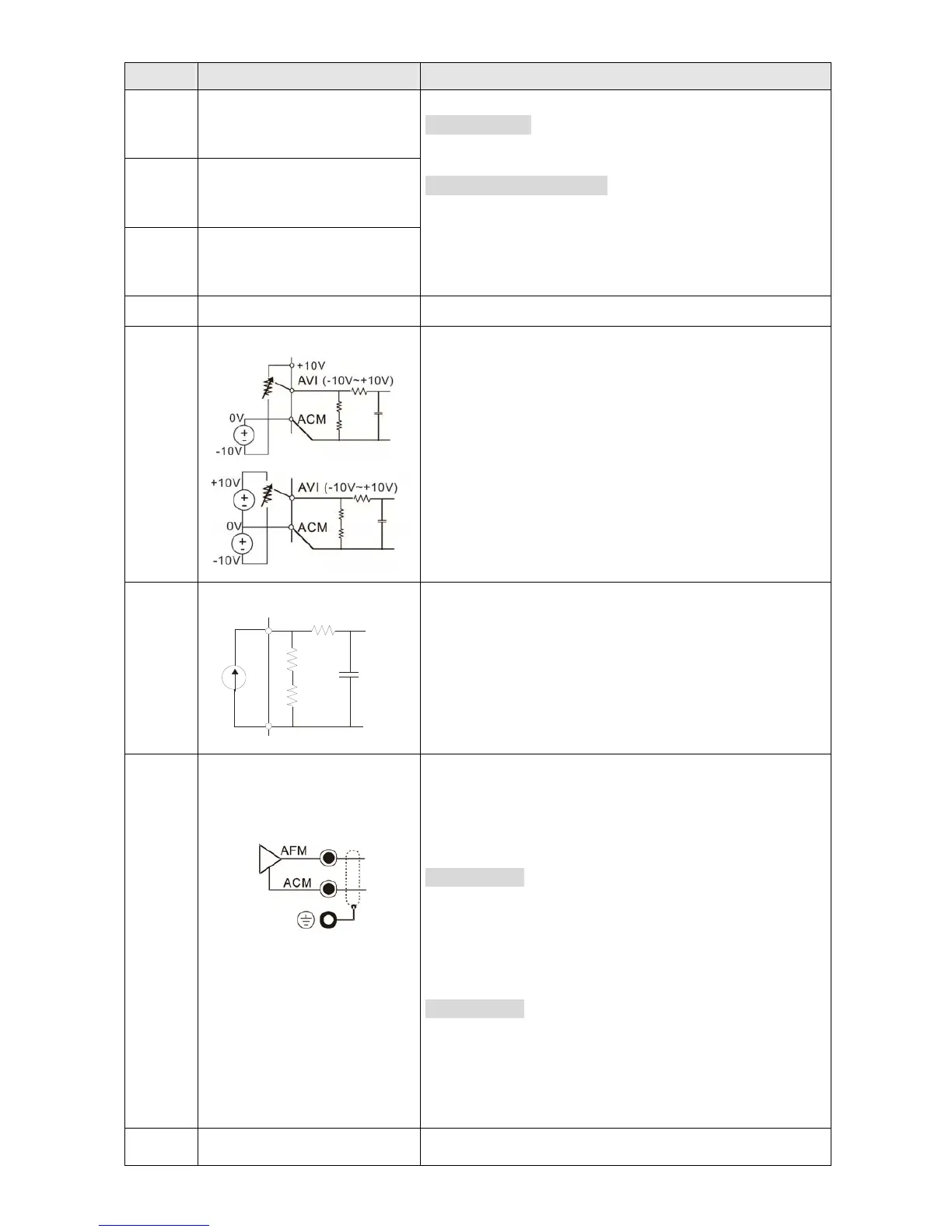
AVI
Analog voltage input
internal circuit
internal circuit
Programmable analog input, see Pr. 03-00
Impedance: 20 kΩ
Range 0~Max. Output Frequency (Pr. 01-00):
0 ~ +10 V / -10 ~ +10 V
Range switching by Pr. 03-00 , Pr. 03-28
ACI
ACI circuit
internal circuit
Programmable analog input, see Pr. 03-01
Impedance: 250 Ω
Range 0~ Max. Output Frequency (Pr. 01-00):
0~20 mA / 4~20 mA / 0~10 V
Range switching by Pr. 03-01 , Pr. 03-29
AFM
Multi-function analog voltage
output
Switch: the factory setting of AFM is 0~10 V (Voltage
mode), use the switch and Pr. 03-31 to change to
current mode (0~20 mA / 4 mA~20 mA). Must follow the
indication on the back side of front cover or page 6-1 of
user manual when using the switch.
Voltage mode
Range: 0~10 V (Pr. 03-31=0) corresponding to the max.
operating range of the control object
Max. output current: 2 mA
Max. Load: 5 kΩ
Current mode
Range: 0~20 mA (Pr. 03-31=1) / 4 mA~20 mA
(Pr. 03-31=2) corresponding to the max.
operating range of the control object
Max. load: 500 Ω
ACM Analog Signal Common Common for analog terminals
 Loading...


