3
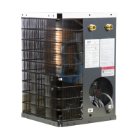
NOTE: Refrigeration condensing unit is designed to run con-
tinuously and should NOT be wired to cycle on/off with the air
compressor.
Operation of dryers with improper line volt-
age constitutes abuse and could affect the dryer war-
ranty.
INSTRUMENTATION
ON/OFF Switch
The dryer is equipped with an ON/OFF switch on the front panel.
A light signals when the dryer is on.
Dryer System Monitor (DSM)
The Dryer System Monitor (DSM) has LED type dew point tem-
perature indicator and operating time control for the electronic
drain valve. When the dryer is running normally, the green LED
will illuminate. If the red LED is illuminated, there is a need for
the dryer's operating condition to be checked. If all LEDs are
illuminated, the sensor for the dew point temperature indicator
has malfunctioned.
The automatic drain valve controls allow the period of drain
opening to be set from 1 second to 9 seconds and drain valve
closed time to be set from 0.5 minutes to 15 minutes. When the
Drain Push-to-Test button (5) is pushed for one (1) second, the
Drain LED (6) will illuminate and the drain port opens with a click.
Automatic Drain Valve
All models are equipped with an electronic drain valve that au-
tomatically discharges condensate from the dryer. Drain valve
operation is controlled by a drain valve timer. The drain opening
can be set from 0.5 seconds to 9 seconds. The drain cycle can
be set from 0.5 minutes to 15 minutes.
Drain valve adjustments are made on the Dryer System Monitor:
1. Press the Selection (4) and Enter (5) buttons at the same
time for 3 seconds, the On Time Setting Mode LED (3) will
start to blink, and the illuminated LED on the Dew Point
Temperature Indicator LED (2) will identify the factory set-
ting for "On Time". (See table)
2. Press and release the Selection button (4) to sequence from
left to right until reaching your selection. The red LED is
not used.
3. To store the "On Time", press the Enter button (5) and set
the "Off Time" using step 2.
4. To store the "Off Time", press the Enter button (5) again.
5. Exiting the Program will cause the Timer Drain to discharge
and begin a new cycle.
NOTE: Failure to perform step 3 within 10 seconds of complet-
ing step 2 will cause the unit to revert back to the previous
setting.
LED (2)
Position
1st 2nd 3rd 4th 5th 6th 7th 8th 9th
On
Time
(sec)
1 2 3 4 5 6 7 8
Continuous
(Drain Trap
Option)
Off
Time
(min)
0.5 1 2 3 5 7 9 10 15
1
7
3 4 10
928
5 6
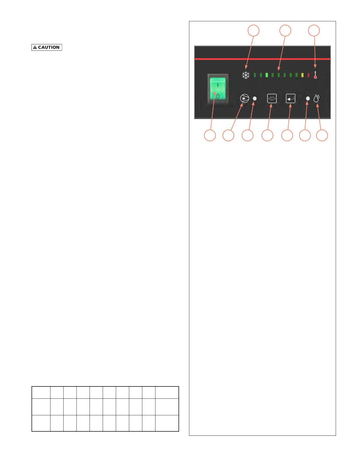
Dryer System Monitor
1. On/Off Switch: Press the top of the switch (I) to turn
the dryer on. Press the bottom of the switch (O) to
turn the dryer off. When the dryer is on, the switch
is illuminated.
2. Dew Point Temperature Indicator: Main portion of
the graphic for the dew point temperature scale.
Green indicates low, red indicates high.
3. Compressor On Light / On Time Setting Mode: Dual
purpose LED indicating light. Illuminates as solid light
when compressor is ON. Blinks On and Off during
setup of the On Time Set Points for the Automatic
Drain Valve.
4. Selection Button: During set up of the Automatic
Drain Valve, when pressed, sequences from left to
right.
5. Drain Push-to-Test Button / Enter Button:
a) Drain Push-to-Test button. When the button is
pressed, the drain valve opens for the time corre-
sponding to the setting established during Drain
Valve setup.
b) Enter button. Stores the "On Time" and "off Time'
drain valve settings established during Drain Valve
setup
6. Drain LED / Off Time Setting Mode: Dual purpose LED
indicating light. Illuminates as solid light when Drain
is closed. Blinks On and Off during setup of the Off
Time Set Points for the Automatic Drain Valve.
7. This is a graphic symbol for the Air Dryer compres-
sor. It simply indicates that the switch is used to turn
the compressor (dryer) on and off.
8. Part of the graphic for the dew point temperature
scale. The snowflake indicates the low (cold) end of
the scale.
9. Part of the graphic for the dew point temperature
scale. The thermometer indicates the high (hot) end
of the scale.
10. This is a graphic symbol for the Drain Valve.
MCGUIRE AIR COMPRESSORS INC
MCGUIRE AIR COMPRESSORS INC