EasyManua.ls Logo

Denon AVC-3000 - Page 10

Denon AVC-3000
66 pages
Print Icon
To Next Page IconTo Next Page
To Previous Page IconTo Previous Page
Loading...
—
AVC
-
3000/30
0
CO
GC
Rea
a
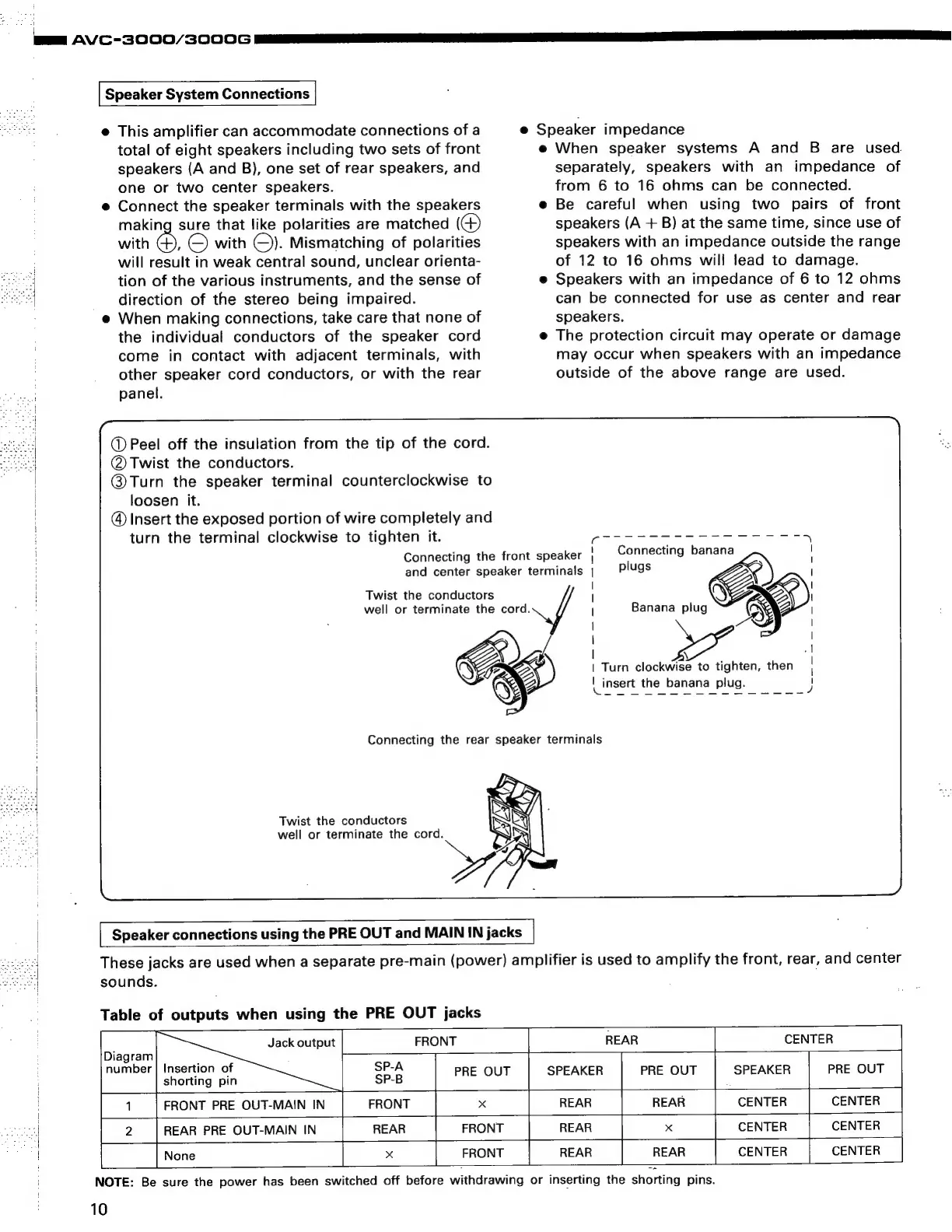
Speaker
System
Connections
e@
This
amplifier
can
accommodate
connections
of
a
total
of
eight
speakers
including
two
sets
of
front
speakers
(A
and
B),
one
set
of
rear
speakers,
and
one
or
two
center
speakers.
e
Connect
the
speaker
terminals
with
the
speakers
making
sure
that
like
polarities
are
matched
(G)
with
en)
©
with
(©).
Mismatching
of
polarities
will
result
in
weak
central
sound,
unclear
orienta-
tion
of
the
various
instruments,
and
the
sense
of
direction
of
the
stereo
being
impaired.
e
When
making
connections,
take
care
that
none
of
the
individual
conductors
of
the
speaker
cord
come
in
contact
with
adjacent
terminals,
with
other
speaker
cord
conductors,
or
with
the
rear
panel.
@
Peel
off
the
insulation
from
the
tip
of
the
cord.
@Twist
the
conductors.
@
Turn
the
speaker
terminal
counterclockwise
to
loosen
it.
@
Insert
the
exposed
portion
of
wire
completely
and
turn
the
terminal
clockwise
to
tighten
it.
Connecting
the
front
speaker
|
and
center
speaker
terminals
|
Twist
the
conductors
well
or
terminate
the
cord.
Twist
the
conductors
well
or
terminate
the
cord.
e@
Speaker
impedance
e
When
speaker
systems
A
and
B
are
used.
separately,
speakers
with
an
impedance
of
from
6
to
16
ohms
can
be
connected.
e
Be
careful
when
using
two
pairs
of
front
speakers
(A
+
B)
at
the
same
time,
since
use
of
speakers
with
an
impedance
outside
the
range
of
12
to
16
ohms
will
lead
to
damage.
e
Speakers
with
an
impedance
of
6
to
12
ohms
can
be
connected
for
use
as
center
and
rear
speakers.
e
The
protection
circuit
may
operate
or
damage
may
occur
when
speakers
with
an
impedance
outside
of
the
above
range
are
used.
Connecting
banana
plugs
|
Banana
plug
|
Turn
clockwise
to
tighten,
then
|
insert
the
banana
plug.
[
Speaker
connections
using
the
PRE
OUT
and
MAIN
IN
jacks
These
jacks
are
used
when
a
separate
pre-main
(power)
amplifier
is
used
to
amplify
the
front,
rear,
and
center
sounds.
Table
of
outputs
when
using
the
PRE
OUT
jacks
Diagram
number
Insertion
of
shorting
pin
Jack
output
FRONT
REAR
CENTER
|
ae
PRE
OUT
SPEAKER
PRE
OUT
SPEAKER
PRE
OUT
FRONT
PRE
OUT-MAIN
IN
FRONT
x
REAR
REAR
CENTER
CENTER
REAR
PRE
OUT-MAIN
IN
REAR
FRONT
REAR
x
CENTER
CENTER
x
FRONT
REAR
REAR
CENTER
|__
CENTER
NOTE:
Be
sure
the
power
has
been
switched
off
before
withdrawing
or
inserting
the
shorting
pins.
10