EasyManua.ls Logo

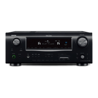
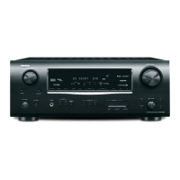
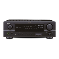
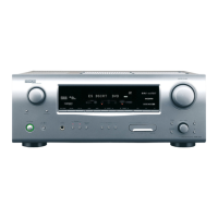
Denon AVR-1909 Service Manual

Denon AVR-1909
161 pages
To Next Page IconTo Next Page
Page #1 background imageLoading...
Page #1 background image
Denon Brand Company, D&M Holdings lnc.
For purposes of improvement, specifications and
design are subject to change without notice.
Please use this service manual with referring to the
operating instructions without fail.
Some illustrations using in this service manual are
slightly different from the actual set.
注 意
サービスをおこなう前に、このサービスマニュアルを
必ずお読みください。本機は、火災、感電、けがなど
に対する安全性を確保するために、さまざまな配慮を
おこなっており、また法的には「電気用品安全法」に
もとづき、所定の許可を得て製造されております。
従ってサービスをおこなう際は、これらの安全性が維
持されるよう、このサービスマニュアルに記載されて
いる注意事項を必ずお守りください。
本機の仕様は性能改良のため、予告なく変更すること
があります。
補修用性能部品の保有期間は、製造打切後 8 年です。
修理の際は、必ず取扱説明書を参照の上、作業を行っ
てください。
本文中に使用しているイラストは、説明の都合上現物
と多少異なる場合があります。
X0383 V.03 DE/CDM 0812
SERVICE MANUAL
AV SURROUND RECEIVER
MODEL JP E3 E2 EK E2A E1C EA
AVR-1909
33
AVR-789
33
AVC-1909
3
Ver. 3
Please refer to the
MODIFICATION NOTICE.

Table of Contents

Other manuals for Denon AVR-1909

Questions and Answers:

Denon AVR-1909 Specifications

General IconGeneral
Speakers connectivity type-
HDMI version1.3a
Product colorBlack
x.v.Color supportYes
Receiver typeSurround
Frequency range10 - 100000 Hz
Audio output channels7.1 channels
Power output per channel (1KHz@6 Ohm)120 W
Power output per channel (20-20KHz@8 Ohm)90 W
HDMI in3
Number of HDMI outputs1
Ethernet LANNo

Summary

SAFETY PRECAUTIONS

LEAKAGE CURRENT CHECK

Check performed before returning the unit to the customer to ensure safety.

Heed the cautions!

Pay attention to labels, seals, and handling instructions for specific parts.

Caution concerning electric shock!

Warning about touching internal metal parts when energized; use precautions.

Caution concerning disassembly and assembly!

Use gloves to protect hands from sharp metal edges during disassembly.

Only use designated parts!

Use parts with same safety properties, especially marked 'z' parts.

Be sure to mount parts and arrange the wires as they were originally!

Restore parts and wire arrangement to original state for safety.

Inspect for safety after servicing!

Check screw, part, wire replacement and insulation after service.

Concerning important safety parts

Parts with special safety properties indicated by 'z' mark must be replaced with designated parts.

DISASSEMBLY

PANEL FRONT SUB ASSY

Step-by-step instructions for removing the front panel sub assembly.

HDMI P.W.B.ASSY

Instructions for disassembling the HDMI power board assembly.

SIRIUS P.W.B ASSY

Instructions for disassembling the Sirius power board assembly.

TUNER PACK

Instructions for disassembling the tuner pack.

CHASSIS BACK SUB ASSY

Instructions for disassembling the chassis back sub assembly.

VIDEO P.W.B ASSY

Instructions for disassembling the video power board assembly.

CAUTION IN SERVICING

Initializing AV SURROUND RECEIVER/AMPLIFIER

Procedure for initializing the receiver/amplifier after component replacement.

JIG to use for servicing

Check mode for µcom/DSP version

µcom/DSP Version Display Mode

How to check the version information of the microcontroller and DSP.

PROCEDURE FOR CHECKING ERRORS

Displaying the protection history

How to access and display the protection history mode.

Clearing the protection history

Warning indication by the STANDBY LED

Describes how the STANDBY LED flashes to indicate protection incidents.

ADJUSTMENT

TROUBLE SHOOTING

1. POWER

Troubleshooting steps for power-related issues.

2. Analog video

2.2. HDMI out

HDMI OUT output NG

Steps to take when HDMI output is not working correctly.

3. HDMI/DVI

3.1. No picture or sound is output

Troubleshooting steps when no picture or sound is output via HDMI/DVI.

SEMICONDUCTORS

2. FL DISPLAY

PRINTED WIRING BOARDS

NOTE FOR PARTS LIST

PARTS LIST OF P.W.B. UNIT

EXPLODED VIEW

PARTS LIST OF EXPLODED VIEW

NOTE FOR SCHEMATIC DIAGRAM

WARNING:

Parts marked 'z' have critical characteristics and must be replaced with specified parts.

CAUTION:

Perform leakage current or line-to-chassis resistance check before returning the unit.

SCHEMATIC DIAGRAMS (1/25)

SIRIUS/2WAY RF UNIT

2CH AMP UNIT

VIDEO UNIT (1/2)

VIDEO UNIT (2/2)

D VIDEO UNIT (1/3)

D VIDEO UNIT (2/3)

D VIDEO UNIT (3/3)

POWER UNIT

SUPPLAY UNIT

REG UNIT

Related product manuals