22
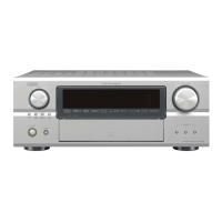
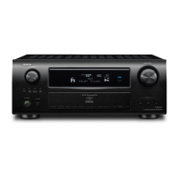
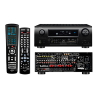
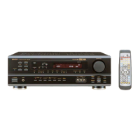
AVR-4306/AVC-4320
66 P26 Z1 SMONIDET I - - - Eu Z I O/L MAIN ZONE's S-monitor connection detect input
(Connected:L )
67 P25 Z1 SSIG.DET I - - - Eu Z I O/L MAIN ZONE's S-signal detect input (H : S-signal
inputted)
68 P24 V.EXPCLK O C - - - Z O/L O/L CLK output for video expander control (TC4094BF)
69 P23 V.EXPD O C - - - Z O/L O/L
DATA output for video expander control (TC4094BF)
70 P22 V.EXPSTB O C - - - Z O/L O/L STB output for video expander control (TC4094BF)
71 P21 V.EXPOE O C - - Ed Z O/L O/L OE output for video expander control (TC4094BF)
72 P20 POSILOW I -
E
↓
L
- Ed Z O/L O/L Temperature detect (Detected : L)
73 P17/INT5 EREQ I -
E
↓
L
- - Z I O/L ETHERNET comm. control pin
74 P16/INT4 REQSOMI I -
E
↓
L
- - I O/L MAIN-SUB µcom comm. control pin
75 P15/INT3 POWER KEY I -
E
↓
L
- Eu Z I O/L Interrupt port for WAIT mode cancel
76 P14/D12 POWER O C - - Ed Z O/L O/L POWER relay control output (H : ON)
77 P13/D11 EPOWER O C - - Ed Z O/L O/L ETHERNET POWER control output (H : ON)
78 P12/D10 232C POWER O C - - Ed Z O/H O/L 232C POWER control pin (STANDBY : H)
79 P11/D9 REDLED O C - - Ed Z O/L O/L POWER/STANDBY LED control pin
80 P10/D8 GRNLED O C - - Ed Z O/L O/L POWER/STANDBY LED control pin
81 P07/D7 H/P DET I - - - Eu Z O/L O/L H/P detect input (Detected : H)
82 P06/D6 FL RST O C - - Ed Z O/L O/L FL DRIVER control pin
83 P05/D5 FL CE2 O C - - - Z O/L O/L FL DRIVER control pin
84 P04/D4 FL CE1 O C - - - Z O/L O/L FL DRIVER control pin
85 P03/D3 FL DATA O C - - - Z O/L O/L FL DRIVER control pin
86 P02/D2 FL CLK O C - - - Z O/L O/L FL DRIVER control pin
87 P01/D1 VSEL A I - Lv - Eu Z O/L O/L
Mazter Volume rotation detect input (Rotary encoder)
88 P00/D0 VSEL B I - Lv - Eu Z O/L O/L
Mazter Volume rotation detect input (Rotary encoder)
89 P107/AN7 ISEL A I - Lv - Eu Z O/L O/L Input selector rotation detect input (Rotary encoder)
90 P106/AN6 ISEL B I - Lv - Eu Z O/L O/L Input selector rotation detect input (Rotary encoder)
91 P105/AN5 KEY3 I - Lv - Eu Z O/L O/L Button input3
92 P104/AN4 KEY2 I - Lv - Eu Z O/L O/L Button input2
93 P103/AN3 KEY1 I - Lv - Eu Z O/L O/L Button input1
94 P102/AN2 ASIGDET I - Lv - - Z O/L O/L Signal detect input
95 P101/AN1 IPOD POWER O C - - - Z O/L O/L Power supply control pin for IPOD charge
96 AVSS AVSS - - - - - - - - AD GND
97 P100/AN0 MODE I - Lv - - Z O/L O/L Destination switching input
98 VREF VREF - - - - - - - - AD ref. +5V
99 AVCC AVCC - - - - - - - - AD +5V
100 P97/SIN4 E_SPIMIEO O C - - - Z O/L O/L ETHERNET comm. control pin
Pin
No.
Pin Name Symbol I/O Type Det
Op
(Int.)
Op
(Ext.)
Res STBY stop Function
Note: Pin No. : Terminal number of microcomputer.
Port Name : The name entered in the data sheet of microcomputer.
Symbol : Symbolized interface function.
I/O : Input or out of part.
“I” = Input port
“O” = Output port
Type : Composition of port in case of output port.
“C” = CMOS output
“N” = NMOS open drain output
“P” = PMOS open drain output
Op : Pull up/Pull down selection information.
“Iu” = Inner microcomputer pull up
“Id” = Inner microcomputer pull down
“Eu” = External microcomputer pull up
“Ed” = External microcomputer pull down
Det : Indicates judging state of input port. Level detection is “LV”; Edge detection is “Ed”; Detection by both shifting is “E&L”;
Serial data detection is “S” (Serial data output is also “S”).
Res : State at reset.
“H” = Outputs High Level at reset
“L” = Outputs Low Level at reset
“Z” = Becomes High impedance mode at reset
STBY : State of port when STANDBY mode.
“O/L” = Output port and “L”
“I” = Input port
Stop : State of port when Stop mode.
“O/L” = Output port and “L”
“I” = Input port
w
w
w
.
x
i
a
o
y
u
1
6
3
.
c
o
m
Q
Q
3
7
6
3
1
5
1
5
0
9
9
2
8
9
4
2
9
8
T
E
L
1
3
9
4
2
2
9
6
5
1
3
9
9
2
8
9
4
2
9
8
0
5
1
5
1
3
6
7
3
Q
Q
TEL 13942296513 QQ 376315150 892498299
TEL 13942296513 QQ 376315150 892498299
http://www.xiaoyu163.com
http://www.xiaoyu163.com
 Loading...