Do you have a question about the Denon AVR-4520 and is the answer not in the manual?
Outlines the procedure and criteria for performing a leakage current check before returning the set to the customer.
Provides general cautions and handling instructions for servicing and inspection procedures.
Details the specifications for the audio amplifier, including rated output and dynamic power.
Outlines specifications for the video section, covering standard and component video connectors.
Covers general specifications such as power supply voltage, consumption, and weight.
Refers to the disassembly procedure and exploded view for the front panel sub assembly.
Refers to the disassembly procedure and exploded view for the left radiator sub assembly.
Refers to the disassembly procedure and exploded view for the right radiator sub assembly.
Refers to the disassembly procedure and exploded view for the power transformer.
Refers to the disassembly procedure and exploded view for the back panel sub assembly.
Details the procedure for updating firmware using the DFW software.
Guides on how to check for the latest firmware and perform the update via DPMS.
Guides on how to insert the USB memory into the unit's USB port for firmware update.
Provides a flowchart for troubleshooting power-related issues, including no power on.
Guides on troubleshooting steps for no sound output in the analog audio section.
Provides a troubleshooting flowchart for issues with no picture or sound when using HDMI to HDMI connections.
Outlines a systematic check for audio output issues, guiding through analog and digital audio blocks.
Shows the schematic diagram for the SPK/SMPS unit.
Lists the major integrated circuits (ICs) used in the device, including their pin configurations.
| Impedance | 8 Ω |
|---|---|
| Receiver type | Surround |
| Frequency range | 10 - 100000 Hz |
| Input sensitivity | 200 mV |
| Audio output channels | 7.1 channels |
| Audio A/D Converter (ADC) | 24-bit/192kHz |
| Signal-to-Noise Ratio (SNR) | 102 dB |
| Power output per channel (1KHz@6 Ohm) | 190 W |
| Power output per channel (20-20KHz@8 Ohm) | 150 W |
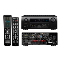
| HDMI in | 7 |
| Composite video in | 4 |
| USB ports quantity | 1 |
| Digital audio optical in | 2 |
| Component video (YPbPr/YCbCr) in | 3 |
| Connectivity technology | Wired |
| Speakers connectivity type | - |
| Audio formats supported | AAC, FLAC, MP3, WMA |
| Wi-Fi | No |
| Ethernet LAN | Yes |
| FM band range | 87.5 - 108 MHz |
| Supported radio bands | AM, FM |
| Product color | Silver |
| Audio decoders | Dolby Digital EX, Dolby Pro Logic IIz, Dolby TrueHD, DTS 96/24, DTS Neo:6, DTS Neo:X, DTS-HD |
| USB 2.0 ports quantity | USB 2.0 ports have a data transmission speed of 480 Mbps, and are backwards compatible with USB 1.1 ports. You can connect all kinds of peripheral devices to them. |
| Apple docking compatibility | Not supported |
| AC input voltage | 230 V |
| AC input frequency | 50 Hz |
| Power consumption (standby) | 0.1 W |
| Power consumption (typical) | 780 W |
| Depth | 423 mm |
|---|---|
| Width | 434 mm |
| Height | 195 mm |
| Weight | 16500 g |