11
About the photos used for "descriptions of the DISASSEMBLY" section
• The shooting direction of each photograph used herein is indicated on the left side of the respective photograph as
"Shooting direction: ***".
• Refer to the diagram below about the shooting direction of each photograph.
• Photographs with no shooting direction indicated were taken from the top of the set.
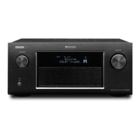
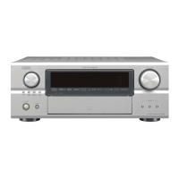
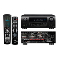
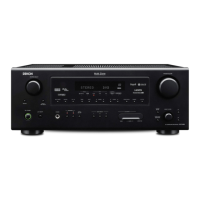
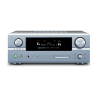
• The photograph is AVR-4520CIE3 model.
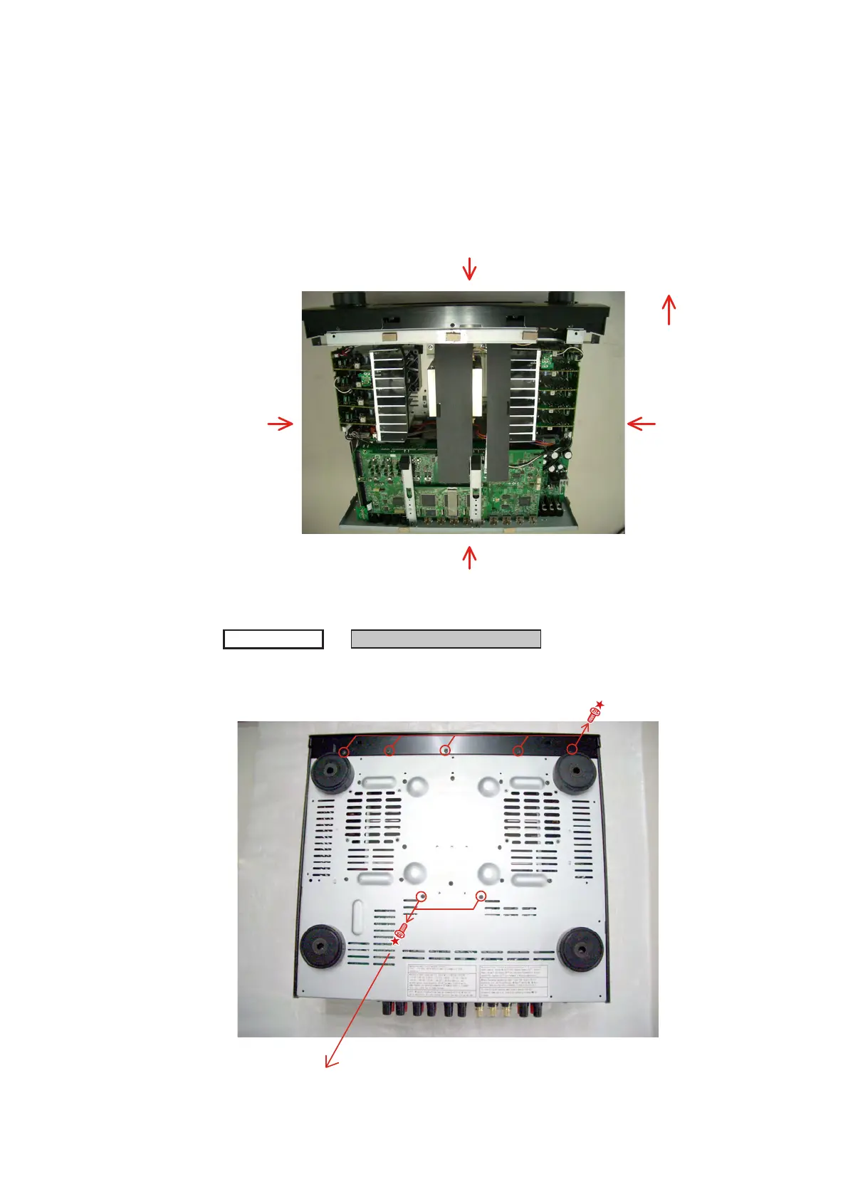
1. FRONT PANEL SUB ASSY
(1) Remove the screws.
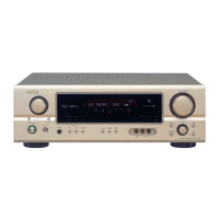
The viewpoint of each photograph
(Shooting direction)
[View from the top]
Front side
Shooting direction: B
Shooting direction: D
Shooting direction: C
Shooting direction: A
TOP COVER
FRONT PANEL SUB ASSY
→
Proceeding :
View from bottom
If the removal is only FRONT PANE, this screw may not be removed.
 Loading...