EasyManua.ls Logo

Denon DRA-565RD Service Manual

Denon DRA-565RD
32 pages
To Next Page IconTo Next Page
Page #1 background imageLoading...
Page #1 background image
D
E
N
O
N
Hi-Fi
AM-FM
Stereo
Reciever
oa
es
Ue
Peay
‘Oe
Is
SERVICE
MANUAL
MODEL
DRA-565RD
MODEL
DRA-S65RD
AM-FM
STEREO
RECIEVER
DRA-565RD
DRA-365RD
TABLE
OF
CONTENTS
OPERATING
INSTRUCTIONS
...
0...
cece
eee
ee
eee
eee
Sled
donate
toe
BAG
a
heat
Ge
ES
2-9
DISASSEMBLY
ois,
ctierda
ls
paced
esc
ete
e
bale
de
dee
tee
Biola
eS
EEN
oh
aoe
aie
Galt
Geared
he
Spe
10,
11
METHOD
OF
ADJUSTMENTS
.
0.0...
cc
cent
ete
ee
eee
tenner
e
eer
nesees
12
CONNECTION
DIAGRAM
OF
MEASURING
INSTRUMENTS
..........-2.-
202
cee
eet
hae
HLS
SEMICONDUCTORS
.....
2...
ce
ccc
cece
e
een
e
nent
cent
nese
eens
en
reer
neaes
13~16
BLOCK/LEVEL
DIAGRAM
(DRA-565RD)
..
6...
eee
ccc
cee
eee
eet
een
nee
nen
ge
Ae
BLOCK/LEVEL
DIAGRAM
(DRA-365RD)
.......-..
beh
be
wibucca
lel
gad
deena
hath
oamedaed
altavug
ane
we
EAMG
17
NOTE
ON
PARTS
LIST
2.0...
cc
cece
ee
te
eee
eee
eee
te
ecate
ie
igda
ae
array
Ree
eae
eR
aR
aI
Seneca
18°
PRINTED
WIRING
BOARD
PARTS
LIST
(DRA-S65RD)
..
0.2.6.
ttre
18,19
PRINTED
WIRING
BOARD
PARTS
LIST
(DRA-365RD)
...
0...
tte
19,
20°
PRINTED
WAIRING
BOARD
PATTERNS
........2.
ccc
eee
cect
tent
tt
tne
es
21~23
1U-2731B
MAIN
UNIT
(DRA-565RD)
..
6.6...
ee
tenet
etter
ene
21
1U-2731
MAIN
UNIT
(DRA-365RD)
.
0.66.
ee
ene
eet
e
eens
22
1U-2732B
TUNER
&
DISPLAY
UNIT
(DRA-S65RD)
2.0...
ete
23
1U-2732
TUNE
&
DISPLAY
UNIT
(DRA-365RD)
.
0...
te
tees
24
WIRING
DIAGRAM
2.0...
00
ec
eee
eee
eee
nen
ene
tere
en
eee
eee
ener
e
eee
ES
25
EXPLODED
VIEW
OF
CHASSIS
AND
CABINET
(DRA-S65RD)
...
6.06.
ee
tee
nts
26
PARTS
LIST
OF
EXPLODED
VIEW
(DRA-S65FD)
«1.0...
nett
nets
27
PARTS
LIST
OF
EXPLODED
VIEW
(DRA-365RD)
...
0...
eee
een
ete
nen
28
EXPLODED
VIEW
OF
CHASSIS
AND
CABINET
(DRA-365RD)
.......
fg
dlan
odode
dante
d
gaat
oe
Ba
wees
29
SCHEMATIC
DIAGRAM
(for
DRA-565RD)
«0...
ee
eee
cette
etree
nets
31
SCHEMATIC
DIAGRAM
(for
DRA-365RD)
....
2.6.
tenes
32
NIPPON
COLUMBIA
CO.
LTD.

Other manuals for Denon DRA-565RD

Question and Answer IconNeed help?

Do you have a question about the Denon DRA-565RD and is the answer not in the manual?

Denon DRA-565RD Specifications

DRA-565RD

Power IconPower
continuous power output80 W + 80 W (4 ohms, 1 kHz)
power consumption145 W
power supplyAC 230V 50 Hz
Tuner Specifications IconTuner Specifications
receiving range FM87.5 ~ 108 MHz
receiving range AM522 ~ 1611 kHz
signal to noise ratio MONO82 dB
signal to noise ratio STEREO78 dB
Input Specifications IconInput Specifications
phono MM input sensitivity and impedance2.5 mV 47 kohms
maximum input level (at 1 kHz) PHONO MM120 mV
CD, VIDEO input sensitivity and impedance150 mV 25 kohms
Weight and Dimensions IconWeight and Dimensions
weight7.2 kg
width434 mm
height130 mm
depth312 mm

DRA-365RD

Power IconPower
continuous power output62 W + 62 W (4 ohms, 1 kHz)
power consumption120 W
power supplyAC 230V 50 Hz
Tuner Specifications IconTuner Specifications
receiving range FM87.5 ~ 108 MHz
receiving range AM522 ~ 1611 kHz
signal to noise ratio MONO82 dB
signal to noise ratio STEREO78 dB
Input Specifications IconInput Specifications
phono MM input sensitivity and impedance2.5 mV 47 kohms
maximum input level (at 1 kHz) PHONO MM120 mV
CD, VIDEO input sensitivity and impedance150 mV 25 kohms
Weight and Dimensions IconWeight and Dimensions
weight6.0 kg
width434 mm
height120 mm
depth312 mm

REMOTE CONTROL UNIT RC-174

Power IconPower
power supply3V DC Two size “AA” (R6) dry cell batteries
Weight and Dimensions IconWeight and Dimensions
weight120 g
width60 mm
height175 mm
depth18 mm

Summary

DENON Service Manual Overview

Model Identification

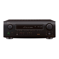
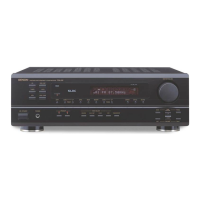
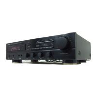
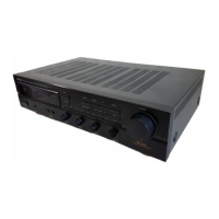
Identifies the DRA-565RD and DRA-365RD AM-FM Stereo Receiver models.

Regional Scope

Manual covers European and U.K. model variations.

Safety and Installation Precautions

Electrical Shock Warnings

Critical warnings about electric shock hazards and user-serviceable parts.

Installation Guidelines

Instructions for correct unit placement, ventilation, and environmental considerations.

Unit Usage Notes and Front Panel

Front Panel Control Overview

General explanation of front panel controls and indicators.

Package Contents and Setup Notes

Included Accessories Checklist

List of items included in the carton with the main unit.

Frequency Step Setting

Instructions for setting the frequency step switch for different regions.

Panel Control Designations and Functions

Front Panel Controls and Indicators

Detailed functions of all front panel buttons, knobs, and display indicators.

Rear Panel Terminals

Description of all input/output terminals, speaker connections, and power outlets.

System Connections and Installation

Component Connectivity Diagrams

Wiring diagrams for connecting audio sources, tape decks, and speakers.

Antenna Installation Guide

Guidelines for installing FM and AM antennas for optimal reception.

Tuning and Memory Operations

Station Presetting and Recall

Procedures for storing, recalling, and clearing preset radio stations.

Advanced FM Tuning Features

Using RDS Search, PTY Search, and TP Search for station discovery.

Remote Control Operation

RC-174 Unit Setup and Use

Instructions for inserting batteries, operating the remote, and its capabilities.

Troubleshooting and Specifications

Troubleshooting Common Issues

Guide to diagnose and resolve common operational problems with the receiver.

Technical Performance Specifications

Detailed electrical and performance data for amplifier and tuner sections.

Disassembly and Servicing

Unit Disassembly Procedure

Step-by-step instructions for dismantling the receiver for maintenance.

Adjustment Procedures

Steps for setting idling current and other internal adjustments.

Measurement Connection Diagrams

Diagrams for connecting test equipment for FM and AM alignment.

Component Identification

Integrated Circuits (ICs)

IC pin allocation and function details, including the TMP87CM71F.

Transistors and Diodes

Lists and diagrams of various transistors, diodes, and LEDs used in the unit.

System Architecture and Diagrams

Block/Level Diagrams

Visual representation of signal paths and functional blocks for both models.

Wiring Diagrams

Overall wiring schematic illustrating interconnections between unit modules.

Parts Lists and Layouts

Main Unit Parts List (DRA-565RD)

Detailed component list for the 1U-2731B Main Unit (DRA-565RD).

Printed Wiring Board Patterns (DRA-565RD)

Visual layout of the circuit traces for the 1U-2731B Main Unit.

Exploded Views of Chassis and Cabinet (DRA-565RD)

Visual breakdown of the unit's physical structure and component placement.

Exploded Parts List (DRA-565RD)

Detailed list of all parts shown in the exploded view for the DRA-565RD.

Exploded Parts List (DRA-365RD)

Detailed list of all parts shown in the exploded view for the DRA-365RD.

Schematic Diagrams

DRA-565RD Circuit Schematic

Detailed electronic circuit diagram for the DRA-565RD receiver.

DRA-365RD Circuit Schematic

Detailed electronic circuit diagram for the DRA-365RD receiver.

Related product manuals