Do you have a question about the Denso RC5 and is the answer not in the manual?
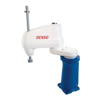
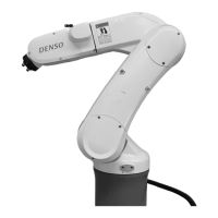
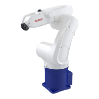
Lists robot models addressed in the manual.
Lists all related manuals in the documentation set and their purpose.
Outlines the structure of the book, including safety and main chapters.
Defines key terms related to robot operation spaces and programs.
Covers introduction to safety and installation environment requirements.
Details environmental requirements for standard and dust-proof types.
Importance of maintaining sufficient service space for robot operations.
Covers placement of control devices, gauges, wiring, E-stop switches, and indicators.
Guidelines for setting up safety fences or enclosures to prevent access.
Alternative safety measures using ropes or chains if fences are not feasible.
Covers motion space, modifications, tool cleaning, lighting, object protection, and warning labels.
Guidelines for safe robot operation and worker precautions.
Establishing and enforcing work regulations for safe operation.
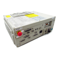
Explains how to identify the controller model from its nameplate.
Details modified deadman switch functions and identification for Robot System "Type A".
Function limiting robot start to a specified device for Robot System "Type A".
Identifies components of the robot controller for VM-D/HM-E series.
Identifies components of robot controllers for other series.
Lists connector pin assignments for different series and encoder connection types.
Details essential specifications like control system, axes, memory, power, and environment.
Shows external dimensions for different robot controller models.
Table showing IPM board locations for various robot series and models.
Block diagram of internal circuits for a typical RC5 controller.
Shows typical system configurations with multiplexed bus encoders.
Diagram of system setup with parallel interface encoders.
Explains the two operating modes: standard and compatible.
Procedure for switching between standard and compatible modes.
Step-by-step guide to switching modes using the teach pendant.
Step-by-step guide to switching modes using a computer via WINCAPSII.
Describes system and user I/O signals used in standard mode.
Describes system and user I/O signals used in compatible mode.
Covers I/O variable declaration, global/local variables, and input commands.
Details SET, RESET, and OUT commands for user output.
Lists system output signals and their functions in standard mode.
Describes the usage of each system output signal in standard mode.
Lists system input signals and their functions in standard mode.
Details function, terminal, and input conditions for the Enable Auto input signal.
Details function, terminal, and input conditions for the Robot Stop input signal.
Details function, terminal, and input conditions for the Step Stop input signal.
Details function, terminal, and input conditions for the Instantaneous Stop input signal.
Details function, terminal, and input conditions for the Interrupt Skip input signal.
Table listing I/O commands and their functions.
General information and diagram illustrating I/O command processing.
Details usage of command, data areas, and odd parity.
Details function, terminal, and input conditions of the strobe signal.
Details function, terminal, and usage of the command processing complete signal.
Details usage, terminal numbers, and conditions for the status area output.
Table listing various I/O commands and their parameters.
Details function, format, and description of the Program Operation Command.
Details command for setting external speed, acceleration, and deceleration.
Details command for reading existing error numbers to the status area.
Details command for substituting values into Type I global variables.
Details command for outputting Type I global variable values to the status area.
Details command for switching robot operation mode from external device.
Details command to clear a robot failure.
Details command to substitute status into internal I/O area.
Details command to output status of internal I/O area to status area.
Illustrates an example setup for starting/stopping robot using I/O signals.
Details functions of display, lamps, and switches on an operating panel.
Outlines procedure and shows I/O signals for start, stop, and operation.
Diagram showing I/O signals for operation preparation and start.
Diagram showing I/O signals for automatic operation and operation end.
Lists system output signals and functions in compatible mode.
Describes the usage of system output signals in compatible mode.
Details function, terminal, usage, and conditions for Auto Mode output.
Details function, terminal, usage, and conditions for Servo ON output.
Details function, terminal, usage, and conditions for CAL Complete output.
Details function, terminal, usage, and conditions for External Mode output.
Details function, terminal, usage, and conditions for Teaching output.
Details function, terminal, usage, and conditions for Program Start Reset output.
Details function, terminal, usage, and conditions for Robot-in-operation output.
Details function, terminal, usage, and conditions for Single-Cycle End output.
Details function, terminal, usage, and conditions for Normal CPU output.
Details function, terminal, usage, and conditions for Robot Failure output.
Details function, terminal, usage, and conditions for Robot Warning output.
Details function, terminal, usage, and conditions for Dead Battery Warning output.
Details function, terminal, usage, and conditions for Error No. output.
Details usage and conditions for Continue Start Permitted and SS mode outputs.
Details function, terminal, and usage of Emergency Stop output.
Lists system input signals and functions in compatible mode.
Details function, terminal, and input conditions for Enable Auto input.
Details function, terminal, and input conditions for Operation Preparation Start input.
Timing chart for operation preparation start signal and related inputs/outputs.
Describes pin assignments for connectors on the robot controller (NPN type).
Pin assignments common to both modes for HAND I/O CN9.
Pin assignment for the I/O POWER connector CN7, common to both modes.
Pin assignment for the RS232C connector CN1.
Describes pin assignments for CN10 and CN8 in standard mode (NPN type).
Pin assignments for the INPUT CN8 in standard mode (NPN type).
Describes pin assignments for CN10 and CN8 in compatible mode (NPN type).
Pin assignments for the INPUT CN8 in compatible mode (NPN type).
Shows circuit configurations and connections for input circuits (NPN type).
Shows circuit configurations and connections for input circuits (NPN type).
Input circuit configuration for Robot Stop and Enable Auto signals.
Shows configuration and connection examples for output circuits (NPN type).
Examples of configuration and connection for emergency stop circuits (NPN type).
Shows examples of connecting I/O power connectors with internal/external power.
Procedures for checking wiring continuity before powering on.
Describes pin assignments for connectors on the robot controller (PNP type).
Pin assignments common to both modes for HAND I/O CN9 (PNP type).
Pin assignment for I/O POWER connector CN7, common to both modes (PNP type).
Describes pin assignments for CN10 and CN8 in standard mode (PNP type).
Pin assignments for INPUT CN8 in standard mode (PNP type).
Describes pin assignments for CN10 and CN8 in compatible mode (PNP type).
Pin assignments for INPUT CN8 in compatible mode (PNP type).
Shows circuit configurations and connections for input circuits (PNP type).
Shows circuit configurations and connections for input circuits (PNP type).
Input circuit configuration for Robot Stop and Enable Auto signals (PNP type).
Shows configuration and connection examples for output circuits (PNP type).
Examples of configuration and connection for emergency stop circuits (PNP type).
Shows examples of connecting I/O power connectors with internal/external power (PNP type).
Procedures for checking wiring continuity before powering on (PNP type).
Lists optional multi-core I/O cables with part numbers and lengths.
Lists recommended connectors, cable standards, and remarks for I/O cables.
Details power supply specifications, pin assignments, and consumption.
Details power supply specifications, pin assignments, and consumption.