11/20166 / 72
6159931430
Issue no: 05
Series: -
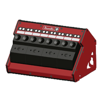
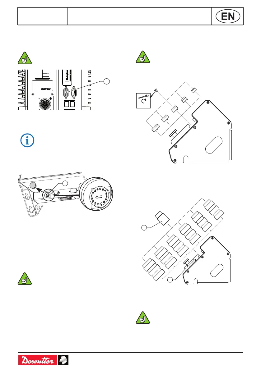
CONTROLLER CONNECTION
● Connect the eBUS cable to the bottom panel
of the controller (see below).
24V-1A is supplied from the controller to
power the socket tray.
9
Legend
9 Controller eBUS port
Max current: 90 mA @ 24V DC.
SOCKET TRAY POSITION
1
Legend
1 Encoding wheel
● Remove the cap from the encoding wheel.
● By using a screwdriver, select the position
number of the socket tray on the eBUS cable:
(1-9 and A-F), 1 being the rst position, F the
last (F=15).
● Do not put the accessory in use when
the encoding wheel is set to "0".
● Put the cap back on the wheel.
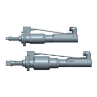
SOCKET INSTALLATION
Internal centering of the socket
Pawn Ø ≤ socket M size Ø.
● Select the pawn and secure it by using the
screw mounted on the socket tray.
M10
M12
M14
M16
M18
0.35 Nm
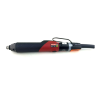
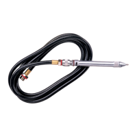
External guiding of the socket
● Select the tube, slide the locking part to block
it and tighten with the knurled knob or the
screw+washer provided in the packing box.
T1
T2
T3
T4
T5
T6
2
1
Legend
1 Socket
2 Locking part
Socket outer Ø ≤ tube Ø.