33
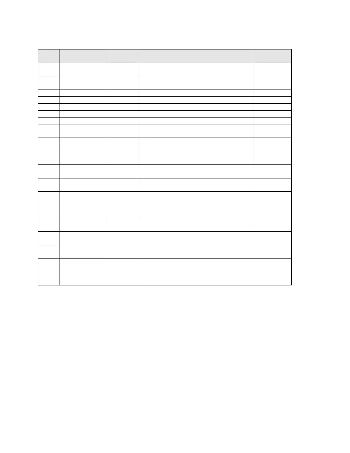
Table 5-1 Tune Mode Parameters
STEP
DESCRIPTION DISPLAY
CODE
AVAILABLE SETTINGS FACTORY
SETTING
1 Local Setpoint LSP +/- Setpoint Limits Input range
minimum
2 Remote
Setpoint
rSP +/- Setpoint Limits Read Only
3 Setpoint 1 Value
SP1 +/- Setpoint Limits Read Only
4 Setpoint 2 Value
SP2 +/- Setpoint Limits Read Only
5 Input Correct iCor ± Span 0
6 Output 1 % Po1 0 to 100% Read Only
7 Output 2% Po2
1
0 to 100% Read Only
8 1st Output Prop.
Band
Pb1 0 to 999.9% of Input Span O%=On/OFF 5.0
9 2nd Output
Prop. Band
Pb2
1
0 to 999.9% of Input Span O%=ON/OFF 5.0
10 Automatic
Reset
ArSt
3
OFF to 99 mins.
59 secs/Repeat
OFF
11 Rate rAtE
3
0 sec to 99 mins.
59 secs/Repeat
0 secs.
12 Manual Reset rSEt
3
0 to 100% for output 1
-100 to 100% for output 2
25%
13 Hysteresis:
Output 1
Output 2
Out 1 & Out 2
HyS1
2
HyS2
1, 2
HySt
1, 2
0.1 to 10.0% of span
0.1 to 10.0% of span
0.1 to 10.0% of span
0.5
0.5
0.5
14 Overlap/
Deadband
SPrd
1
-20 to 20% of Pbl and Pb2 0%
15 Setpoint Ramp
Rate
SPrr
5
1 to 9999 units/hour and OFF OFF
16 Remote
Setpoint Offset
rSPo
4
-1999 to 9999 0
17 Output 1 Cycle
Time
Ct1
3
.5, 1, 2, 4, 8, 16, 32, 64, 128, 256, 512
(seconds)
32
18 Output 2 Cycle
Time
Ct2
1, 3
.5, 1, 2, 4, 8, 16, 32, 64, 128, 256, 512
(seconds)
32
1 Does not appear unless output 2 has been selected
2 Does not appear unless instrument is configured for on-off control
3 Does not appear unless instrument is configured for proportional control
4 Does not appear unless remote setpoint has been selected
5 Does not appear unless ESPr is enabled in Enable Mode