48
8.2 Hardware Definition Code
The Hardware Definition Code is used to represent the hardware installed (input type,
Output 1 type, Output 2 type and Output 3 type); this must be compatible with the
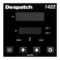
hardware actually installed. It can be accessed, with the instrument in Configuration
Mode (with a prompt inPS, etc. displayed), by simultaneously depressing the DOWN
and SCROLL keys. The displays will show "XXXX" (where X represents any number) in
the upper display and "dEFn" in the lower display, where:
the first (left-most) digit is input type:
1 = RTD/Linear mV
2 = Thermocouple
3 = Linear DC mA
4 = Linear DC V
the second digit is Output 1 type:
1 = Relay
2 = SSR
3 = DC 0-10 V
4 = DC 0-20 mA
5 = DC 0-5 V
7 = DC 4-20 mA
the third digit is Output 2 type:
O = Output 2 not installed
1 = Relay (control or alarm 2)
2 = SSR (control or alarm 2)
3 = DC 0-10 V (control only)
4 = DC 0-20 mA (control only)
5 = DC 0-5 V (control only)
7 = DC 4-20 mA (control only)
the fourth digit is Output 3 type:
O = Output 3 not installed
1 = Relay (alarm 1 only)
2 = SSR (alarm 1 only)
3 = DC 0-10 V (retransmit only)
4 = DC 0-20 mA (retransmit only)
5 = DC 0-5V (retransmit only)
7 = DC 4-20 mA (retransmit only)