L
lsanchezSep 12, 2025
What does General Fault mean on Det-Tronics UD10?
- NNicholas YoungSep 12, 2025
A General Fault indicates an unspecified fault. Verify correct power wiring and supply voltage. Consult the factory.
What does General Fault mean on Det-Tronics UD10?
A General Fault indicates an unspecified fault. Verify correct power wiring and supply voltage. Consult the factory.
What to do if Det-Tronics Monitor shows Low Cal Line?
If the monitor displays 'Low Cal Line', it means the Cal line is shorted. Check the wiring.
What does Cal Line Active mean on Det-Tronics Monitor and how to fix it?
If 'Cal Line Active' appears at start-up, it means the Cal line is active. Ensure that the Cal line wiring is not shorted and the switch is open.
What does Low Fault mean on Det-Tronics UD10 Monitor?
A Low Fault means the detector output is lower than the specified limit. Verify correct sensor type and calibration.
How to fix Input Loop FLT on Det-Tronics UD10?
If you're experiencing an Input Loop FLT, it indicates a fault in the sensor or sensor loop. You should check the sensor wiring, calibrate the sensor, and ensure that the sensor type matches the configuration.
How to resolve a Comm Fault on Det-Tronics UD10 Monitor?
A Comm Fault indicates a communication fault. Check the detector wiring and power supply.
What to do if Det-Tronics UD10 Monitor shows Sensor Mismatch?
If the monitor displays 'Sensor Mismatch', it means the installed sensor type doesn't match the configuration. The sensor type must match the configuration. Change either the sensor or the configuration.
What does Dirty Optics mean on Det-Tronics UD10 and how to clean it?
If you see 'Dirty Optics', it means the detector optics are dirty. Perform the cleaning procedure as described in the detector manual, then perform calibration.
How to fix Blocked Optic Fault on Det-Tronics UD10?
A Blocked Optic Fault means that the optical path is blocked. Locate and remove the obstruction from the optical path.
What causes Zero Drift on Det-Tronics UD10 and how to resolve it?
Zero Drift indicates that the sensor signal has drifted negative. This can happen if the device was calibrated with background gas present. Recalibrate the detector, purging with clean air if needed.
Describes the UD10's recommended applications and capabilities.
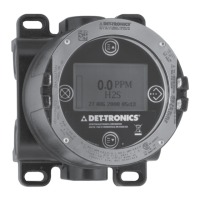
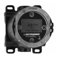
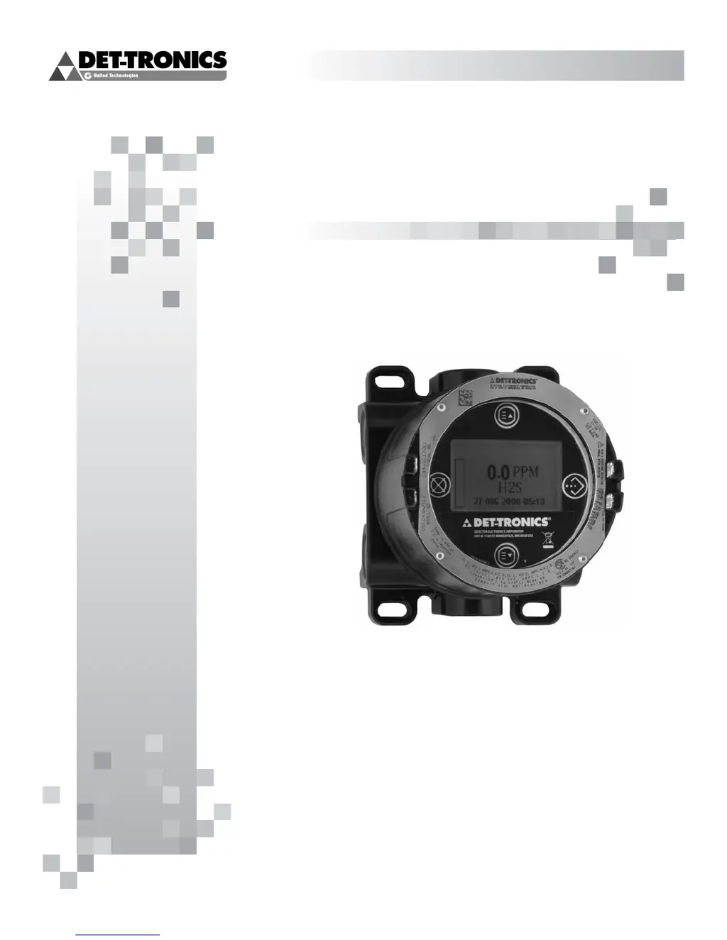
Details the UD10's functions, I/O, and visible outputs.
Provides device status info and field programming capability via HART.
Explains using magnets to navigate menus and adjust parameters.
How to access main menu and fault menu using magnets.
Details the 4 output relays and their configurations.
Describes the two operating modes for the 4-20 mA output.
Details support for Modbus RS485 and Foundation Fieldbus.
Information logged by the UD10, including events and calibration data.
Essential safety warnings for installation and operation.
Identifying the vapor and its properties for optimal detector placement.
Determining best locations based on leak sources and air patterns.
Requirements for power supply voltage, noise, and cable type/length.
Proper methods for grounding wiring cable shields.
Jumper settings for 4-20 mA loop and Fieldbus configuration.
Illustrations of UD10 wired to a PLC in various configurations.
Recommended lubricants for installation and future removal.
Steps for initial startup and selecting the correct operating mode.
Setting the Real Time Clock and configuring latching alarms.
Procedures for calibrating the 4-20 mA input and output loops.
Calibrating the detector's signal when using HART communication.
Calibrating the UD10's output loop (zero and gain).
Trimming the UD10 input for HART-enabled detectors.
Tests for verifying system functions like Self-Test, Response, and Loop Test.
Enabling password protection to restrict configuration changes.
Identifies display-related faults and recommended corrective actions.
Identifies device-specific faults and recommended corrective actions.
Details operating voltage, power, temperature, and humidity.
Specs for current output, relay contacts, and response time.
Detector compatibility and available measurement units.
Procedure for returning devices for service, including RMI number.
Details FM, CSA, ATEX, IECEx, and SIL certifications.
Information on ordering parts and understanding the model matrix.
Contact information for ordering assistance and support.
Wiring diagram for connecting a HART handheld communicator.
Navigating the UD10 menu with a HART communicator.
Wiring diagram for connecting UD10 directly to GT3000 detector.
Recommended mounting orientation for the GT3000 detector.
Performing sensor replacement and maintenance on a live system.
Steps for calibrating GT3000 using its magnetic switch.
Steps for initiating calibration of GT3000 from the UD10.
Wiring diagram for connecting UD10 to PIR9400 detector.
Important notes regarding grease and sensor contact for PIR9400.
Recommended horizontal installation position for PIR9400.
How to change UD10 mode for PIR9400 detector.
Steps to calibrate PIR9400 using the UD10 display or PIRTB box.
Wiring diagrams for connecting UD10 to various sensor types.
Recommended horizontal installation position for PIRECL.
Steps to calibrate PIRECL using the UD10 display.
Steps to calibrate PIRECL using its magnetic switch.
Wiring diagram for connecting UD10 to OPECL sensor.
Requirements for mounting OPECL modules to a stable structure.
Steps to initiate zero calibration of OPECL from the UD10.
Information on OPECL transmitter lamp fault conditions.
Menu navigation for OPECL detector with UD10.
Wiring diagrams for NTMOS sensor connection.
Important installation notes for the NTMOS sensor.
Recommended mounting orientation for NTMOS assembly.
Notes and procedure for calibrating the NTMOS sensor.
Step-by-step procedure for calibrating NTMOS sensor via UD10.
Menu navigation for NTMOS detector with UD10.
Wiring diagrams for connecting UD10 to C706X sensor.
Specific wiring requirements for C706X installations.
Steps for installing and wiring the C706X sensor.
Steps to calibrate C706X sensor using the UD10 display.
Menu navigation for C706X sensor with UD10.
Wiring diagram for connecting UD10 to CGS sensor.
Critical notes on lubricants, flame arrestor, and sensor type for CGS.
Wiring requirements for CGS sensor installations, including distance limits.
Steps for installing and wiring the CGS sensor.
Using calibration mV signals to estimate sensor remaining life.
Using K-Factors for calibration with gases other than the calibration gas.
Wiring diagram for connecting UD10 to Model 505/CGS sensor.
Information regarding proper installation of the Model 505 sensor.
Recommended mounting orientation for the Model 505/CGS sensor.
How the UD10 operates with generic 4-20 mA sensors.
Setting upper/lower range values and measurement units for generic sensors.
Configuring low/high fault thresholds and alarm levels.
Setting alarm latching and notes on generic sensor calibration.
| Operating Temperature | -40°C to +75°C (-40°F to +167°F) |
|---|---|
| Humidity | 0-100% RH |
| IP Rating | IP66 |
| Output | 4-20 mA |
| Power Supply | 12-30 VDC |
| Housing | Stainless steel |
| Approvals | ATEX, IECEx |
| Measurement Range | 0-100% LEL |
| Range | Up to 28 m (90 ft) |