11
95-8704
2.7
6
5
4
3
2
1
16
15
14
13
12
11
SHIELD
SHIELD
COM 1 A
COM 2 A
COM 1 B
COM 2 B
PWR SHIELD
PWR SHIELD
+Vin
+Vin
–Vin
–Vin
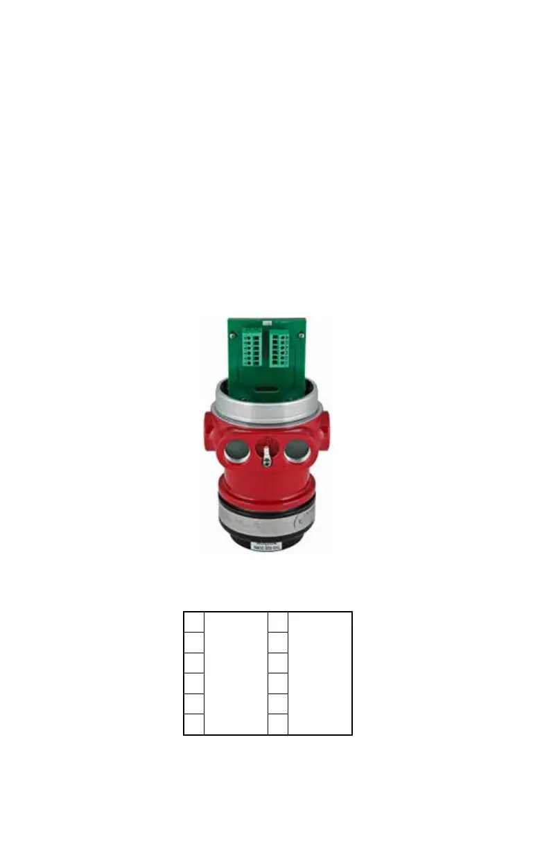
Figure13—X3301 Terminal Block (EQP Model)
Figure14—Wiring Terminal Identication for X3301 EQP Model
EQP Model
1. Connect external wires to the appropriate
terminals inside the device junction box,
shown in Figure 13. See Figure 14 for
terminal identification.
2. Connect the shield of the power cable to
“earth ground” at the power source.
3. Connect shields for the LON cable as
indicated. See Figure15.
NOTE
DO NOT ground any shields at the detector
housing.
4. With input power disconnected, set the
device network address (see the “Setting
Device Network Addresses” section of this
manual for switch setting procedure).
5. Check all field wiring to be sure that the
proper connections have been made.
6. Replace the device cover and apply input
power.
7. Make the final sighting adjustments and
use a 14 mm hex wrench to ensure that the
mounting arm assembly is tight.
NOTE
Refer to the Eagle Quantum Premier system
manual, number 95-8533, for information
regarding power requirements, network
communication cable requirements, and
conguration.