5
95-8704
2.7
CAUTION
The wiring procedures in this manual are
intended to ensure proper functioning of the
device under normal conditions. However,
because of the many variations in wiring
codes and regulations, total compliance to
these ordinances cannot be guaranteed. Be
certain that all wiring complies with the NEC
as well as all local ordinances. If in doubt,
consult the authority having jurisdiction
before wiring the system. Installation must
be done by a properly trained person.
CAUTION
To prevent unwanted actuation or alarm,
extinguishing devices must be disabled prior
to performing system tests or maintenance.
CAUTION
The multispectrum IR ame detectors are
to be installed in places where the risk of
mechanical damage is low.
ATTENTION
Remove the protective cap from the front of
the detector before activating the system.
ATTENTION
Observe precautions for handling
electrostatic sensitive devices.
INSTallaTION
NOTE
The recommended lubricant for threads
and O-rings is a silicone-free grease (p/n
005003-001) available from Det-Tronics.
Under no circumstances should a lubricant
containing silicone be used.
DETECTOR POSITIONING
Detectors should be positioned to provide
the best unobstructed view of the area to be
protected. The following factors should also be
taken into consideration:
• Identify all high risk fire ignition sources.
• Be sure that enough detectors are used to
adequately cover the hazardous area.
• Be sure that the unit is easily accessible for
cleaning and other periodic servicing.
• Verify that all detectors in the system are properly
located and positioned so that any fire hazards
are within both the Field of View (FOV) and
detection range of the detector. The Q1201C
Laser Aimer is recommended for establishing the
detector's FOV. Refer to the "High Resolution Field
of View Diagrams" section for specific information
regarding detector range and FOV.
• The detector should be aimed downward at
least 10–20 degrees to allow lens openings to
drain. See Figure1. The detector should be
positioned so that its FOV does not cover
areas outside the area that requires ame
detection monitoring. This will minimize the
possibility of false alarms caused by activities
outside the area requiring protection.
• The detector must be mounted on a rigid
surface in a low vibration area.
• Dense fog, rain, or ice can absorb IR radiation
and reduce the sensitivity of the detector. To
ensure optimum performance, be certain that the
internal optical heater is enabled on detectors
that are used in applications where snow, ice,
and condensation are likely to occur.
Figure1—Detector Orientation Relative to Horizon
CENTER AXIS
OF DETECTOR
FIELD OF VIEW
CENTER AXIS
OF DETECTOR
FIELD OF VIEW
INCORRECT
CORRECT
NOTE: DETECTOR MUST ALWAYS BE AIMED
DOWNWARD AT LEAST 10 TO 20 DEGREES.
D1974
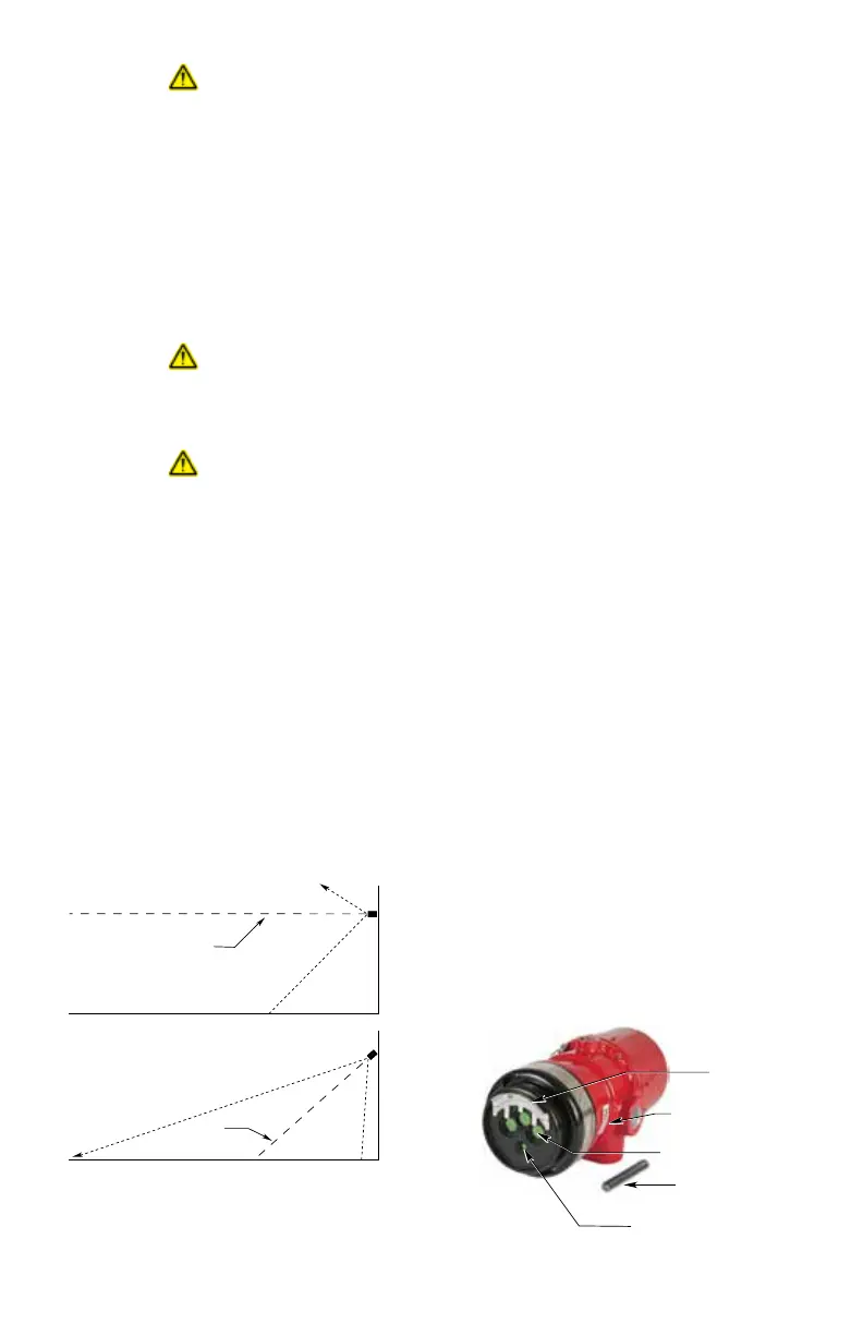
VIEWING WINDOW (3)
o
i
PLATE
PLACE MAGNET
HERE TO INITIATE
MAGNETIC o
i
o
i
MAGNET
DETECTOR
F2068
Figure2—Front View of the X3301