27
2
Hardware Installation
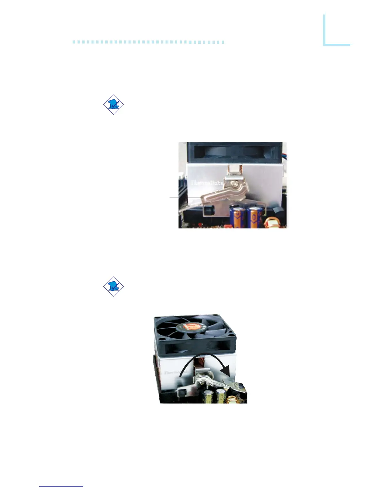
4. Hook the other side of the retention clip (the one near the
retention lever) so that the holes on the retention clip also fit
into the retaining tabs of the retention module base.
Note:
You will not be able to secure the fan and heat sink
assembly in place if it did not fit properly onto the
retention module base.
Retention lever
6. Connect the CPU fan’s cable connector to the CPU fan connec-
tor on the system board.
5. Move the retention lever to its opposite side then push it down
to lock the fan and heat sink assembly to the retention module
base.
Note:
Make sure there is sufficient air circulation across the CPU
fan and heat sink.