1 Introduction
ECO 9099 SOP05-5090F Rev.00 Effective Date: 12/20/18 Page 20 of 58
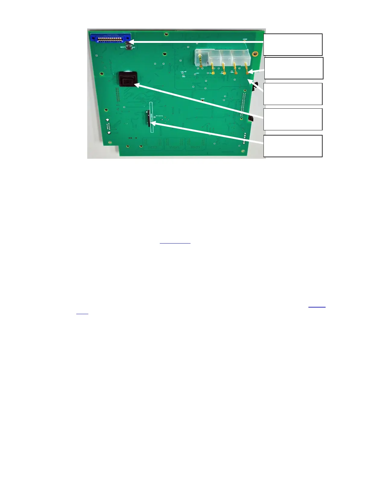
Figure 1-19 CPU Board, Front
To install the CPU board, certain steps should be taken to ensure proper placement.
1. Ensure RFID board is installed with its components and antenna facing the Electrode Pins.
2. Pull each Electrode Pin out slightly so that they extend beyond their normal positions. This
will prevent Electrode Pins from being pushed too far into the socket.
3. Place board on alignment pin. (Figure 1-16
)
4. Check that Electrode Pins are placed in front case without pushing pins into their sockets.
5. Also verify RFID board is not dislodged.
6. Secure CPU Board to the front case using the screws and plastic washers, previously
removed. Leave screws slightly loose.
7. Check that each Electrode Pin is entirely visible through the Electrode mating holes. (
Figure
1-19)
Optical Sensor
RFID Board
Connector
Electrode Pogo
Pin
Printer
Connector
Electrode Pogo
Pin Socket