Transmitters 9 November 2001 87
Next Chapter
Tran sm it te r
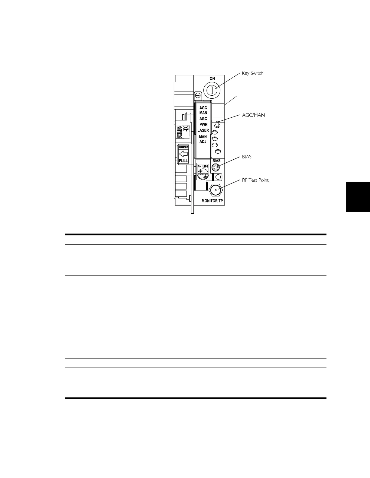
Test Points and Controls Test points and controls are mounted on the front panel for
easy access.
CUST
FACT
MAN
Label indicates AGC options
and toggle positions.
Label Description
Key Switch Activates / deactivates laser. Allows the operator to “lock out” (by
removing the key) the transmitter for maintenance. (Note: Laser
operates only when the shield that covers the optical connection is
installed).
AGC/MAN
For more information, see
“AGC Labeling and Toggle
Positions” on page 88.
The 200-TX, 700-TX, and 800C-TX transmitters offer two AGC
settings: Factory-set AGC Active and Manual Mode (no AGC).
The 800E-TX and 800G-TX transmitters offer three AGC settings:
Customer-set AGC (optimized OMI) Active, Factory-set AGC Active,
and Manual Mode (No AGC).
MAN ADJ Manual gain control. When the AGC switch is in manual, an operator
may adjust the RF drive level to the laser.
When using customer-set AGC function (CUST setting) with 800E-TX
and 800G-TX transmitters, use the manual gain control to set the AGC
level.
BIAS DC test point. Use digital voltmeter to measure laser bias. (10 mV/mA).
RF Test Point RF drive level monitor test point (–20 dB relative to the transmitter’s
RF input level). Used to adjust the RF drive to the optimum level. (See
specifications.) For example, a transmitter with a rated input of
+15 dBmV, should be adjusted to a level of –5 dBmV at the test point.
 Loading...