108 9 November 2001 Transmitters
Checking Laser Bias
Current
Monitor and record laser bias current regularly to find out
how much variability is normal for your transmitter. (For
example, a 0.1 - 0.2 mA change per month may be normal
for your transmitter.) Check any change that is greater than
the typical laser current progression for your module.
Normally, laser bias currents
increase slightly as the laser
ages. Further, laser bias
currents differ from
transmitter to transmitter, so
there is no correct bias
measurement.
Record the laser bias current
at initial installation. In
general, for most transmitters,
a change of more than
10 mA from the initial
installation value warrants
further investigation.
Check Laser Bias Current as follows:
1. If the laser is off, turn it on by turning the key clockwise.
The LASER LED will light.
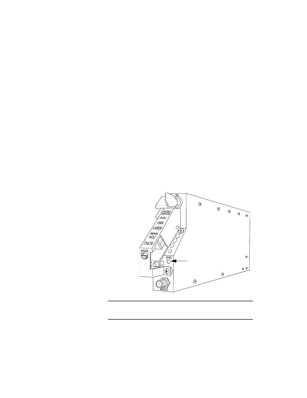
2. Insert the positive test lead from the voltmeter into the
laser bias test point, labeled Bias, on the transmitter.
Connect the negative lead to ground.
3. At this test point, 10 mV = 1 mA. To convert the voltage
measurement to amperage (mA), first express the
voltage in millivolts; then, divide this number by 10. (For
example, 0.35 Volts at the laser bias testpoint equals 350
mV, which equals 35 mA.)
Proceed to “Connecting the Optical Fiber” on page 109.
Figure 48. Laser Bias Test Point
Use the laser bias test point to check the laser bias current.
Laser Bias Test Point