Transmitters 9 November 2001 119
Next Chapter
Tran sm it te r
4. With a small, non-conducting alignment tool, adjust the
manual gain control until the levels measured at the test
point are 20 dB below the RF input level specification.
Turn the control clockwise to increase the drive level; turn
the control counterclockwise to decrease the drive level.
The manual gain control lets you adjust the RF drive level
by ± 3 dB. For greater adjustment, check and adjust the
level of RF signals entering the transmitter.
End of Procedure.
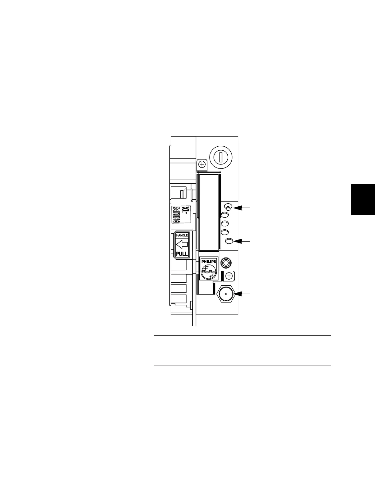
Figure 55. RF Drive Level
Adjust the RF drive level using a non-conducting alignment tool to
turn the manual gain control.
AGC
MAN
PWR
AGC
LASER
BIAS
ON
MONITOR TP
MAN
ADJ
714-TX
Toggle AGC/MAN switch
down for manual mode.
Turn manual gain control
clockwise to increase the
level. Turn counterclockwise
to decrease the level.
Connect a spectrum
analyzer (or suitable meter)
to the test point.
 Loading...