13
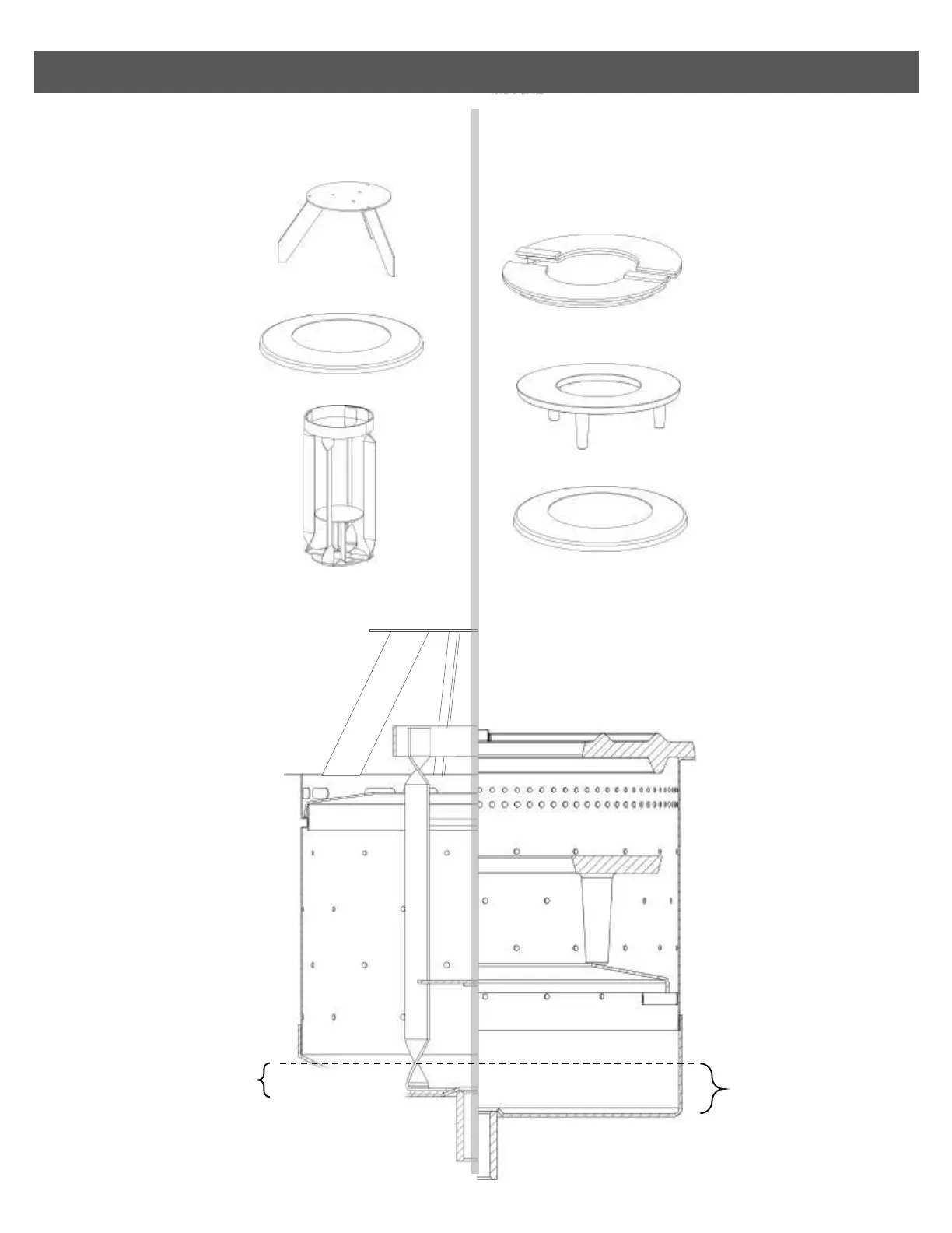
INTERNAL BURNER COMPONENTS
6-inch
burner components
7-inch
burner components
Superheater
6” Burner ring
Low sulfur baffle
Cast iron split ring set
Cast iron leg ring
7” S/S base ring
A.
B.
C.
D.
E.
F.
ATLANTIC, BEAUFORT*
*Discontinued
ADRIATIC, BERING
BRISTOL, PACIFIC
6 INCH BURNER 7 INCH BURNER
A.
B.
C.
D.
E.
F.
A. Low Sulfur Baffle (LSB)
#03-090
The purpose of the low sulfur
baffle is to reflect rising heat
back onto the superheater
keeping it hotter than it
would otherwise remain.
B. Burner Ring
#03-040
The burner ring narrows the
path of the fuel vaporized at
the bottom of the hot burner,
concentrating the fumes and
mixing them with air for
balanced combustion.
C. Superheater
#03-060
The superheater stands on
the bottom of the burner and
protrudes up into the flames
above the burner ring. Its
purpose is to transmit heat to
the bottom of the burner,
keeping it hot in order to
vaporize fuel.
D. Cast Iron Split Rings
#04-070
The split rings encircle the
opening of the burner pot
similarly to the 6 inch burner
ring, concentrating and mixing
vaporizing fuel and air for
balanced combustion.
E. Cast Iron Leg Ring
#04-060
The greater heat of a 7 inch
burner is absorbed and reliably
distributed through the cast iron
leg ring which sits at mid-height
inside the pot.
C. Stainless Steel Base Ring
#04-050
The base ring provides a ledge for
the leg ring above to rest on. Like
the 6 inch version, this ring must
be oriented lip down, creating an
upward funnel to concentrate
rising vapor.
It’s all about heat!
The natural draft burners are
a bowl, into which fuel enters
from below. In a cold burner,
lighting this fuel will result in
a dirty, sooty oil fire. Heat
must accumulate before the
burner is ready to start
vaporizing fuel.
See page 35-37 for more
details on how to correctly
light the appliance.
Priming the burner
To get a burner hot, some
priming fuel must be burned.
Filling the bottom of the
burner, lighting the puddle of
oil and letting it burn until
almost consumed will
introduce enough heat to
start vaporizing fuel.
See pages 38-39 for more
details on tips to help balance
combustion.
Fuel Inlet
OIL LEVEL
of 7” burner
OIL LEVEL
of 6” burner
5/8
th”
1
”
FIG 12
FIG 13
FIG 14