5. MAINTENANCE
SYSTEM MAINTENANCE
Gravity
Fuel Tank
Main Fuel Tank
41
1
1
3
4
5
6
8
7
2
2
1
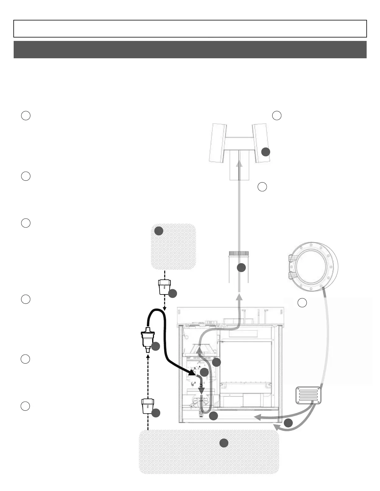
FUEL TANKS
Incomplete or noisy combustion in the burner can often be traced back to
contamination in the fuel tank. Sounds of sizzling or bubbling from the burner
are a sign that moisture within the fuel is evaporating on contact.
Contaminated fuel will make combustion more difficult to balance.
Organic and inorganic sludge accumulate within diesel tanks over time. Diesel
fuel is likely to take on a darker hue when contaminated with sludge, and
contaminated fuel will restrict fuel flow in the fuel lines and cause the moving
parts of the metering valve to seize up and fail to meter consistently.
2
FUEL FILTERS
Fuel filters must be installed between the fuel tank and the metering valve. If
your install uses a fuel pump the filter must be located on the fuel line before
the pump. Fuel filters must be inspected regularly and their filtration elements
replaced when necessary. When not regularly maintained a fuel filter may
restrict fuel flow or become ineffective.
See page 48, fig 82, for fuel filter element replacement
3
FUEL PUMP
Fuel pumps can be used to feed the appliance from
a main fuel tank if the appliance is not receiving
fuel from a gravity feed tank. Because fuel pumps
rely on power and pressure to deliver fuel to the
appliance and have several moving parts, they can
become a source of fuel flow issues. The most
common issues that prevent pumps from delivering
fuel are loss of pressure caused by air leaking into
the fuel lines, and pumps that may have seized due
to running dry.
See page 44 for pump cleaning instructions
Understanding how to go about maintaining a natural draft diesel appliance is simplified if you learn to view the installation as a single system – it is best viewed as
a single system that converts liquid diesel fuel into heat & exhaust.
When we consider the install as a single system, we can see that ensuring flow through the whole system is crucial to its trouble-free operation. Fuel must be
allowed to flow consistently, the burner must heat the liquid fuel and not collect it, while the chimney must be allowed to develop a strong enough draft to suck
exhaust up and out of the cabin. If any of these functions fails or becomes restricted, flow in other parts of the system will also become affected, reducing the
effectiveness of the whole.
4
METERING VALVE
The fuel metering valve maintains the
operating oil level for the appliance, and it
meters out the correct amount of fuel for each
setting. Sticky fuel residue built up inside the
metering valve will prevent its mechanism from
moving smoothly and result in an inconsistent
oil level.
See page 43, fig 87, for valve cleaning
instructions
5
BURNER FUEL LINE
Any debris or blockage inside the fuel line
connecting the metering valve to the burner
may interrupt fuel delivery to the burner. The
fuel line should be cleaned regularly to prevent
deposits from building up inside.
See page 42, fig 83, for fuel line cleaning
instructions
6
BURNER
The burner must vaporize the fuel entering it in
order to maintain balanced combustion. In order
for the burner to vaporize fuel, it must absorb
enough heat. A burner can be prevented from
absorbing enough heat by carbon deposits inside it
which must be cleaned out. Air flow to the burner
must also be maintained. If carbon deposits have
formed they may be choking the burners air holes.
See page 42, fig 84, for burner cleaning instructions
9
AIR SUPPLY
Trouble keeping the flames above the
burner ring, or problems with smoke
being drawn into the cabin, can both
be caused by a lack of fresh air supply .
Fresh air is used by the appliance to
support combustion and must be
resupplied at the same rate as it is
being used up. If fresh air supply is
limited, pressure in the cabin may
become negative, stopping draft within
the chimney and drawing smoke into
the cabin.
7
8
CHIMNEY
If chimney pipes become lined with soot on
the inside. This will reduce the draft
generated inside. A chimney that is not kept
clean will suffer a reduction in draft that will
affect the rest of the appliance.
See page 42 for chimney cleaning
9
CHIMNEY CAP
The chimney cap is the most likely
chokepoint for carbon and soot to
accumulate and choke off the draft. If
draft is limited by the condition of the
chimney or cap, combustion inside the
appliance becomes vulnerable to
extinguishing due to backdraft..
FIG 81
 Loading...