Chapter 2: PRE Hardware Overview and Stand-Alone Operation
9
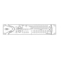
Phase Switch and LEDs
This switch applies phase reversal to individual
channels. When lit (green), Phase LEDs indicate
which channels have phase reverse enabled.
High-Pass Filter Switch and LEDs
This switch applies a high-pass filter to individ-
ual channels. When lit (green), HPF LEDs indi-
cate which channels have the high-pass filter
enabled.
Each PRE channel includes a high-pass filter
with a center frequency of 85 Hz and a roll-off of
–18 dB/octave. Use the high-pass filter to re-
move microphone proximity effects, hum, rum-
ble, wind, and other low frequency sounds.
Channel Mute Switches and LEDs
Each PRE channel has a dedicated Mute switch
to mute input signal. The respective Mute LED
lights when muting is enabled.
Channel Select Switches and LEDs
These switches are used to “focus” one or more
channels for editing. When lit (green), the
Channel Select LED indicates that the channel
can be edited.
The following channel controls can be edited:
• 48V Phantom Power; see “48V Switch and
LEDs” on page 8.
• Phase Reverse; see “Phase Switch and
LEDs” on page 9.
• Pad; see “Pad Switch and LEDs” on page 8.
• Insert; see “Insert Switch and LEDs” on
page 8.
• High-Pass Filter; see “High-Pass Filter
Switch and LEDs” on page 9.
• Mic/Line/Instrument Source Switching; see
“Source Switch and LEDs” on page 7.
• Input Gain; see “Gain/Param and Input
Gain” on page 14.
When PRE is powered off, channel select states
are stored in memory and are subsequently re-
stored at power up.
Line/Inst 1 and 2
The front panel includes two 1/4˝ balanced/un-
balanced TRS jacks, with Tip wired hot (or “+”),
Ring cold (“–”), and Sleeve ground. These jacks
mirror Line/Inst Inputs 1 and 2 on the back
panel. Connecting to the front panel Line/Inst
input will break a connection made to the re-
spective back panel Line/Inst input.
Use these jacks for convenient access to high im-
pedance instrument inputs.