Chapter 3 HYBRID Coater Service Manual ver1.1
20
3.9 Head with Connection PCB
The Connection PCB EL-04875 is connected to the EL-04873 Control PCB. All cables
between these two PCB’s are flexible and shielded cables. Besides connectors this PCB only
contains electronics to convert the signals of the Ø encoder to rigid RS-422 signals. The
upper limit sensor of the Z movement and the vane switch detecting the limit of the Ø
movement are connected to this PCB. On the head also the stepper motors for Z and Ø are
located.
NOTE: IN CASE OF A HC-100 NO Ø STEPPER MOTOR, VANE SWITCH OR
ENCODER ARE PRESENT!
On the bottom side of the Connection PCB a number of flat cable connectors are present.
They are used for the connections to the Dispense Head PCB. See wiring diagram HC-0200-
0107 for HC-100 and HC-0200-0108 for HC-200)
Appendix I shows more detailed information about the I/O of this PCB.
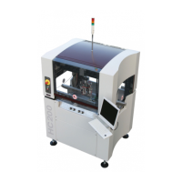
Following figures show details of the Ø encoder (only applies to the HC-200).
This figure shows the sensor for the
upper Z movement. The sensor has an
optical indication showing the status of
its output.
The indication is on when the ring on
top of the spline shaft is up.
On the right side the stepper motor for
the Ø movement is present. The
output of this stepper motor is
mounted onto a gear box.
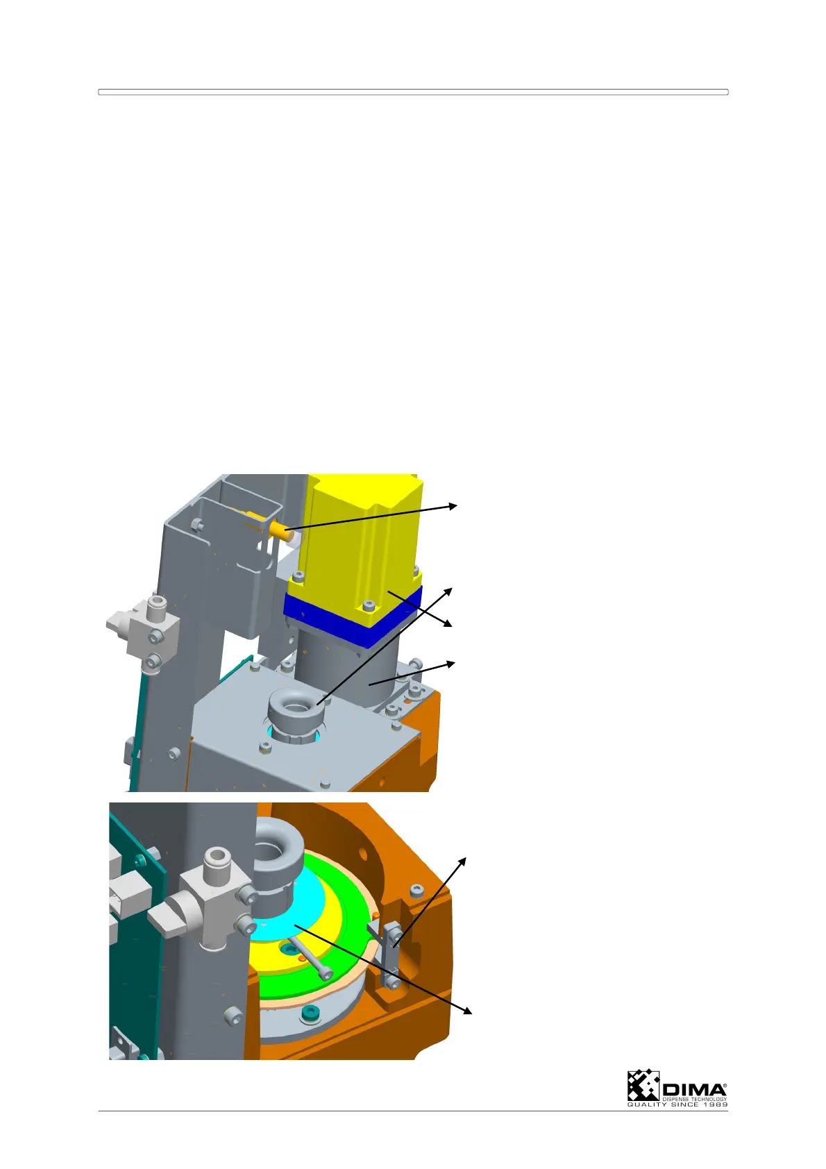
This figure shows the vane switch for
the limit of the Ø movement. The
cover which is normally on this
compartment is not shown in this
figure.
Encoder disk.