HYBRID Coater Service Manual ver1.1 Chapter 4
35
ATTENTION: Note where you loosen the connections in order to be able to make similar
connections on the new Flexible Cable Duct in the same place. For removing the Flexible
Cable Duct see also Section 9.8.
For electrical connections see Appendix C
For pneumatic connections see Chapter 7.
4.8 Installing Options HC-1160 and HC-1170
The Conveyor HC-1160 and HC-1170 are of similar lay-out. The difference is that a HC-1160
is a chain conveyor and that the HC-1170 is a belt conveyor with clamping. With the HC-
1160 chain conveyor the chain tension is set at the DIMA factory. When the chain needs to
be tensioned; don’t adjust is too tight! With the HC-1170 belt conveyor the belt tension is set
at the DIMA factory. When the belt needs to be tensioned; adjust it by moving the stepper
motor in its slots. Don’t adjust the belt too tight! In the middle it should go up or down about
10mm.
4.8.1 Placing/Adjusting Stopper Pin/Product Detect Sensor of
Conveyor
Placing and Adjusting procedures of the Stopper Pin and the Product Detect Sensor at the
HC-1160 and HC-1170 are identical.
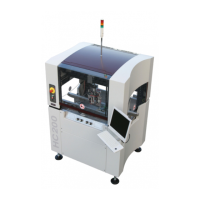
A The stopper pin has to be placed on the desired position first. The standard position of
the stopper pins (the most right position) results in a large working area. When the
coating head can’t reach the desired locations of the product, then the working area can
be reduced, by placing the stopper pins to the left.
B Hole #3 fits the actual stopper pin and holes #2 are intended for the attachment bolts.
With adjusting knob #4 is used for adjusting the upward speed of the Stopper Pin.
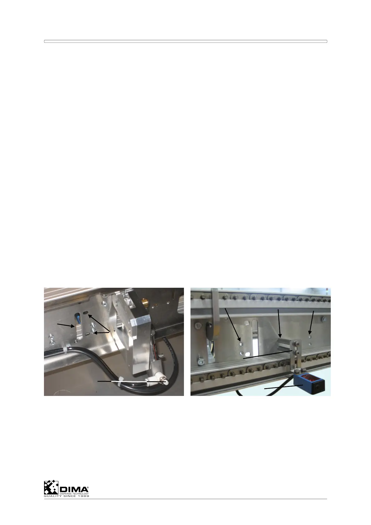
C With the belt conveyor standard the product detect sensor (#8) is placed in the position
(#5) nearest to the stopper pins. Eventually is can be placed one position (#6) further
away from the stopper pins.
D For the pin conveyor standard the product detect sensor (#8) is placed in the middle
position (#6) to the stopper pins. Eventually is can be placed one position (#7) further
away from the stopper pins.
E This depends whether the product reaches the stopper pins easily or not. This can be
caused by jamming or spinning. When speed and weight of the product are low the
sensor can be placed in position close to the stopper pins. When necessary there is an
1
2
3
4
8
7
5 6
9