HYBRID Coater Service Manual ver1.1 Chapter 4
33
NOTE: See the Section ‘HC-1320 Barrel/Syringe Empty Detection’ in the User Manual of
the HybridC, for adjustment.
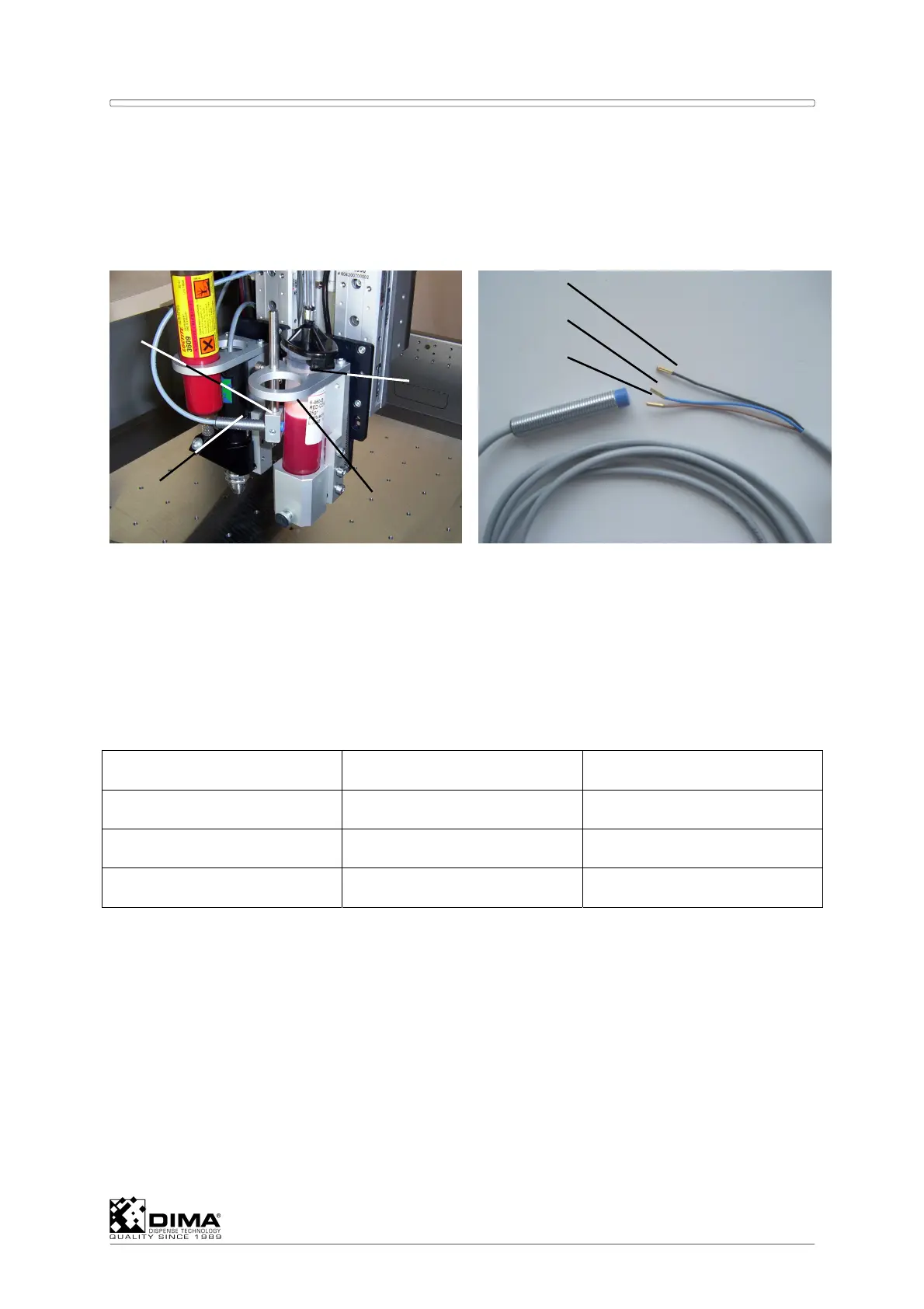
A Mount the correct bracket (#1) and the height arm (#2) too. Mount the sensor (#3) in the
height arm and place the metal disc (#4) in the desired barrel or syringe. Connect the
plug from the sensor to the corresponding socket on the rear of the Coating Head.
NOTE: Remember; Unit 1 is connected through the first D25 connector on the rear of the
Coating Head on PCB EL-04879. Unit 2 corresponds to the second D25 connector
and so on. See also the ‘Coating Head’ Section of the User Manual. Concerning the
digital inputs of the D25 connector see Appendix I for I/O Assignment.
B With the HC-100 the wires of the sensor (#3) have to be connected to the corresponding
D25 connector as follows: Here the wires (#5, 6, and 7) have to be connected to the next
free pins in this D25 connector according to the following example.
EXAMPLE: D25 Connector to #P11 (this can also be P12, P13, or P14)
D25 connector on #P11 Pin allocation Standard
Black wire (signal) 8, or 10, or 12, or 14 12
Brown wire (24V) 7, or 9, or 11, or 13 11
Blue wire (ground) 15, or 16 15
The black wire (signal) assigns which sensor input (Sensor In) from Appendix I is used. Here
the standard #12 assigns it to StdSensorIn01. From this the Level Empty Detection can be
configured on the HybridC screen in Options/Configuration/ then I/O and Digital Inputs
under Ref. all the way down till reaching StdSensorIn01. Here the checkbox Inv has to be
marked. Now the PC can find the sensor. In the same window under Dispensers the
corresponding dispenser has to be opened. Then under Level detection, the checkbox has
to show LevelSensor.
Open Options/Test Machine Parts, then I/O under Name, the corresponding level sensor
appears and can be tested there.
C With the HC-200 the wires of the sensor (#3) have to be connected to the corresponding
location on the PCB EL-04806 as follows: The corresponding connectors of a unit are to
the right hand side of it. The blue wire (ground) has to be soldered to one lead (pointing
inwards to ‘A’) of one resistor found at location ‘A’, and indicated by the white line.
3
1
2
4
5
6
7