10
bottom of the switch and push the switch out the front
panel.
Properly orient the new switch and reconnect all of the 6.
wiring clips and connections as before.
Push the switch through the front control panel until 7.
the Retainer Clips snap the switch into place, then
reassemble the rebox in reverse order as above.
!
NOTE: When placing bottom panel back onto unit,
position the metal lip from under the control panel between
the rubber spacers (attached to the bottom panel) and the
sheet metal of the bottom panel.
Heater Switch Replacement
CAUTION: If unit was operating prior to servicing allow
at least 10 minutes for lights, heating elements and top
panel to cool off to avoid accidental burning of skin.
WARNING: Disconnect power before attempting any
maintenance to reduce the risk of electric shock or damage
to persons.
Remove the rebox from the mantel.1.
Lay unit on its back.2.
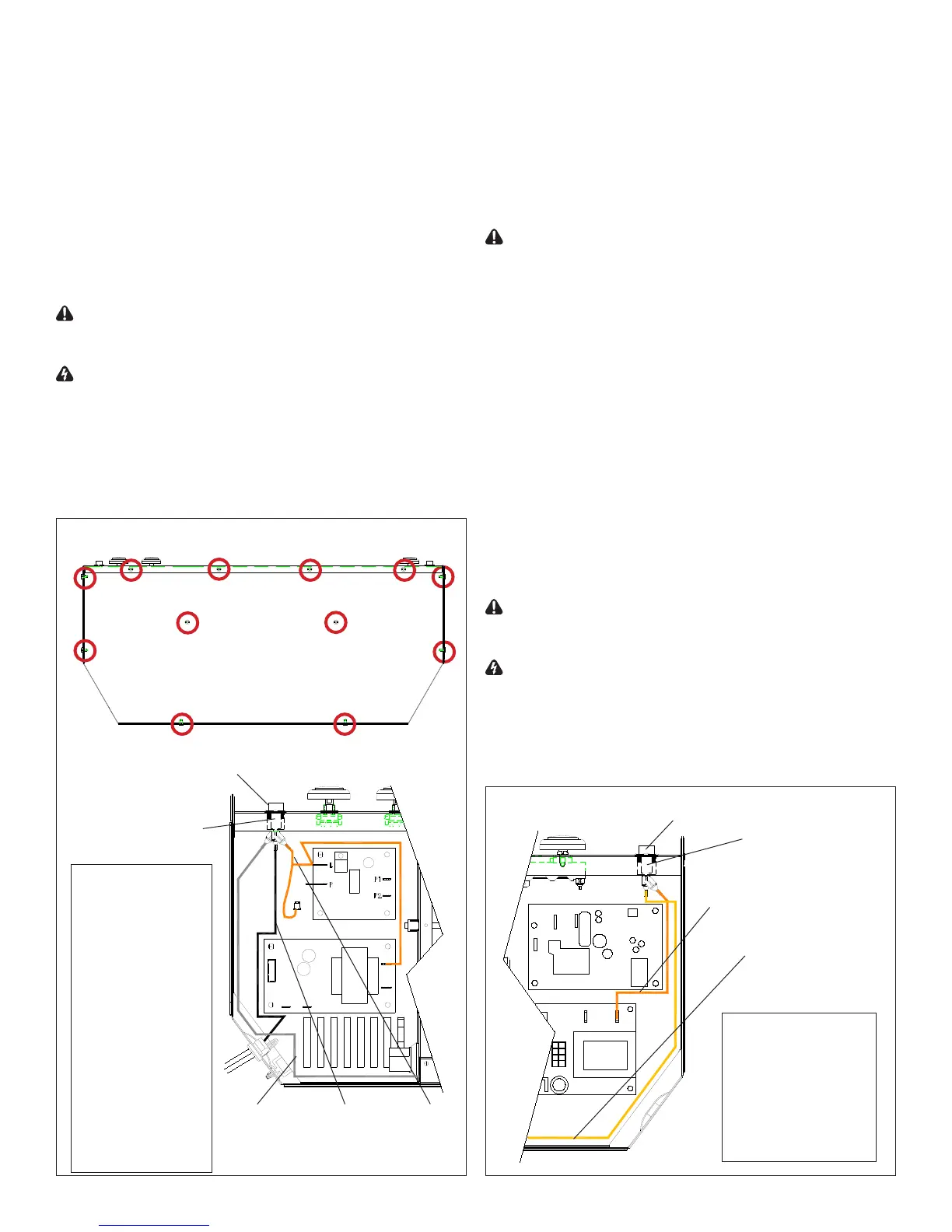
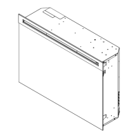
Remove the 12 Philips screws that fasten the bottom 3.
cover to the rest of the rebox. There are: two (2)
screws on each side; two (2) screws on the back panel
(you may have to tip the bottom of the rebox up if it is
laying on its back), four (4) screws in the front directly
under the control panel; and two (2) screws on the
bottom of the rebox (Figure 8). The bottom panel is
now free to be removed.
Locate the Heater Switch mounted on the control panel 4.
on the right side (Figure 10, page 11) and disconnect
the two (2) wiring clips noting their original locations.
CAUTION: Internal wire colors may not be the same
within the unit being serviced as those shown. To avoid
damage to the unit, damage to property or personal injury,
ensure wires are reconnected to match their original
locations.
Depress the two (2) retainer clips on the top and 5.
bottom of the switch and push the switch out the front
of the rebox.
Properly orient the new switch and reconnect all of the 6.
wiring clips and connections as before.
Push the switch through the front control panel until 7.
the Retainer Clips snap the switch into place, then
reassemble the rebox in reverse order as above.
!
NOTE: When placing bottom panel back onto unit,
position the metal lip from under the control panel
between the rubber spacers (attached to the bottom
panel) and the sheet metal of the bottom panel.
Light Dimmer Replacement
CAUTION: If unit was operating prior to servicing allow
at least 10 minutes for lights, heating elements and top
panel to cool off to avoid accidental burning of skin.
WARNING: Disconnect power before attempting any
maintenance to reduce the risk of electric shock or damage
to persons.
Remove the rebox from the mantel.1.
Lay unit on its back.2.
Remove the 12 Philips screws that fasten the bottom 3.
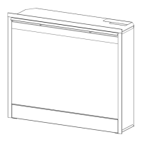
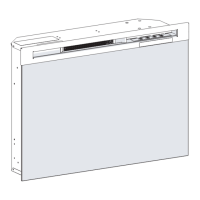
Figure 9
3-Position Switch
Retainer Clips
(One top, one bottom)
Figure 8
Screws To Remove
Wire 1: Dark orange
piggy-back wire
from bottom
terminal of switch
to: top, left terminal
of Dimmer Control
and; to one of 3
wire connectors.
Wire 2: Black,
smooth edged wire
from power cord to
middle terminal of
switch.
Wire 3: Grey wire
from top terminal
of switch to
opposite side of
rebox.
Wire 1Wire 2Wire 3
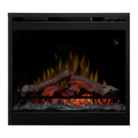
Figure 10
Heater Switch
Retainer Clips
(One top, one bottom)
Wire 1: Dark orange
wire from bottom
terminal of switch to
top, right terminal of
Log Driver (DF2608).
Wire 2: Yellow wire
from top terminal of
switch to other side of
rebox.
Wire 1
Wire 2