12
board where possible) until the clasps of the mounting
studs snap the control board into place.
Properly orient the Potentiometer attached to the 8.
replacement control board, push it through the front
control panel and anchor it in place using the retaining
nut removed in step 5.
Disconnect one of the wire leads from the original 9.
control board (which are still connected to parts
within the rebox) and immediately connect it to the
new control board’s terminal, matching its position.
Continue with the remaining wires (there are four (4)
wires which are piggy-backed together in pairs, and the
cable connector which leads to the Flicker Motor) using
the same procedure.
CAUTION: Internal wiring and colors may not be the
same within the unit being serviced as those shown. To
avoid damage to the unit, damage to property or personal
injury, ensure wires are reconnected to match their original
locations.
Follow steps 1 through 3 in reverse order to 10.
reassemble the rebox.
!
NOTE: When placing bottom panel back onto unit,
position the metal lip from under the control panel between
the rubber spacers (attached to the bottom panel) and the
sheet metal of the bottom panel.
Flicker Motor/Flicker Rod Replacement
CAUTION: If unit was operating prior to servicing allow
at least 10 minutes for lights, heating elements and top
panel to cool off to avoid accidental burning of skin.
WARNING: Disconnect power before attempting any
maintenance to reduce the risk of electric shock or damage
to persons.
Remove the rebox from the mantel.1.
Lay unit on its back.2.
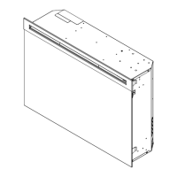
Remove the 12 Philips screws that fasten the bottom 3.
cover to the rest of the rebox. There are: two (2)
screws on each side; two (2) screws on the back panel
(you may have to tip the bottom of the rebox up if it is
laying on its back), four (4) screws in the front directly
under the control panel; and two (2) screws on the
bottom of the rebox (Figure 8). The bottom panel is
now free to be removed.
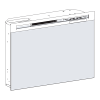
Locate Flicker Rod and Flicker Motor in the base 4.
assembly (Figure 13).
Gently pull the Flicker Rod to the right as far as 5.
possible into the rubber bushing (Figure 13).
!
NOTE: When removing the Flicker Rod, damage may
occur if bent excessively. If the Flicker Rod is damaged,
replace to insure proper operation.
Cautiously bend the Flicker Rod enough so that the 6.
remaining end of the Flicker Rod clears the plastic
bushing on the left (Figure 14).
Remove the Flicker Rod by pulling it free from the 7.
rubber bushing on the motor shaft (Figure 14).
Before removing the Flicker Motor, cut the Flicker Motor 8.
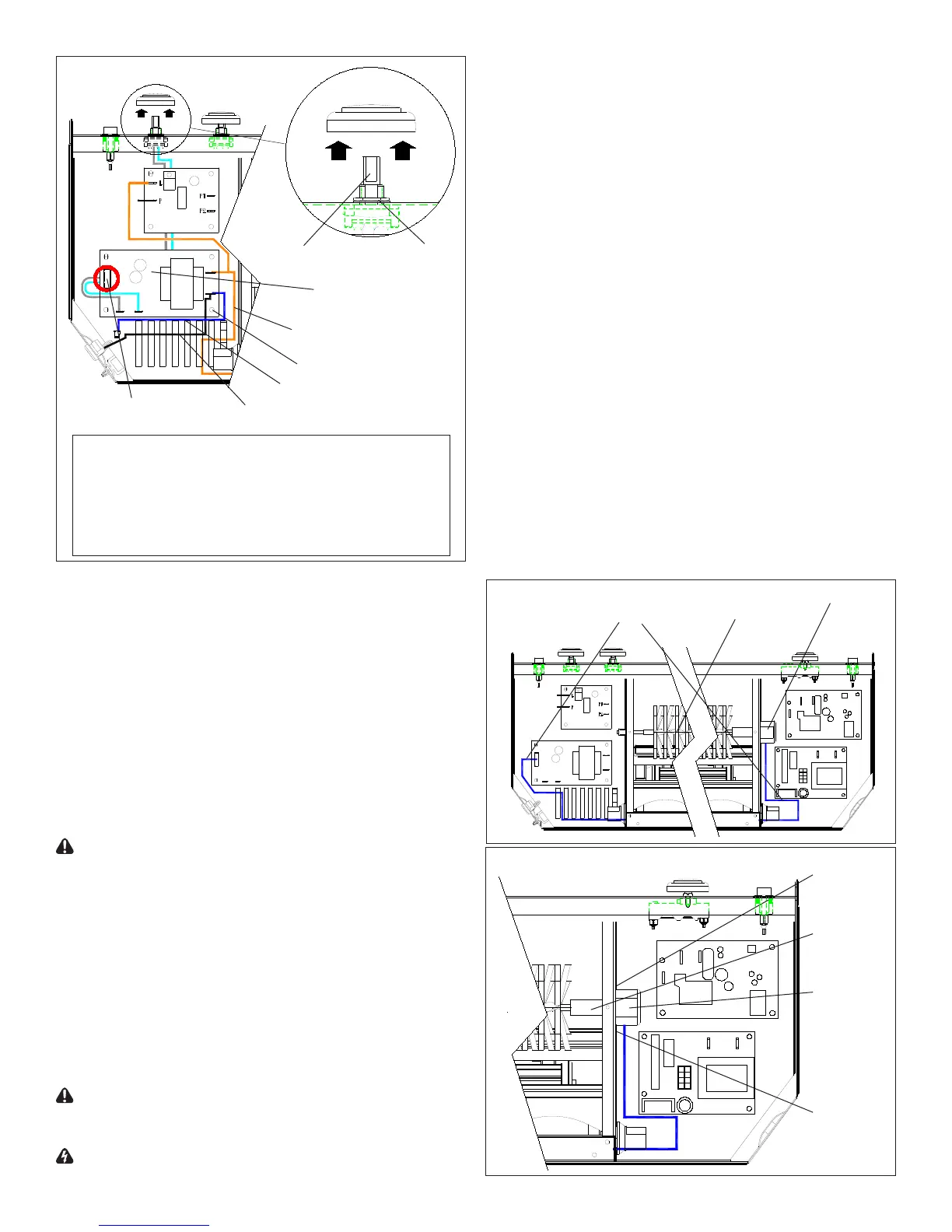
Figure 12
Retaining
Nut
Potentiometer
Mounting Studs (4)
Flame Speed
Control Board
Wire 2
Wire 1
Wire 1: Dark orange piggy-back wire from top, right
terminal of Flame Speed Control board to: top, right
terminal of Light Dimmer board and; other side of rebox.
Wire 2: Blue wire from bottom, right terminal of Flame
Speed Control board to one of 3 wire connectors.
Wire 3: Black wire from bottom, right terminal of Flame
Speed Control board to power cord.
Wire 3
Cable connector
for Flicker Motor
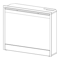
Figure 13
Flicker
Rod
Flicker
Motor
5 Color
Cable
Flicker
Motor
Mounting
Screw
Rubber
Bushing
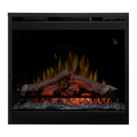
Figure 14
Mounting
Screw