14
Slide fireplace out from mantel.1.
Open the bi-fold doors and steel curtain.2.
Pull the front edge of the plastic ember bed or plastic 3.
grate up and forward until the rear tab releases from
the ledge located at the bottom of the partially reective
glass (Figure 6).
!
Only handle the log set by the ember bed.
!
Log set ts tightly into rebox, some force may
be necessary to remove.
Set log set in front of replace.4.
Disconnect the log set LED wire harness from unit 5.
(Figure 5).
Pull the Flicker Rod to the far right, then bend it carefully 6.
to free and lift the left side out of the mounting bracket
(Figure 15).
!
When removing the Flicker Rod, damage may
occur if bent excessively. If the Flicker Rod is damaged,
replace to insure proper operation.
Remove Flicker Rod (replace and reassemble if Flicker 7.
Motor does not need to be changed at this point).
Before removing the Flicker Motor, cut the Flicker Motor 8.
wires (ve (5) in total) close to the Flicker Motor end with
wire cutters.
Remove the rubber bushing from the motor shaft by 9.
applying needle nose pliers to the motor shaft and twist
the rubber bushing off of the motor shaft.
Remove the motor by unscrewing the two (2) Philips 10.
screws that attach the motor to the mounting bracket
(Figure 15).
Discard old Flicker Motor.11.
Pick up new Flicker Motor and cut wire leads to 3 1/2 12.
inch long with wire cutters.
Using one of the supplied wire connectors from the 13.
Replacement Part Kit, place one (1) yellow wire from the
new Flicker Motor and the yellow wire cut in step 9 into
each terminal.
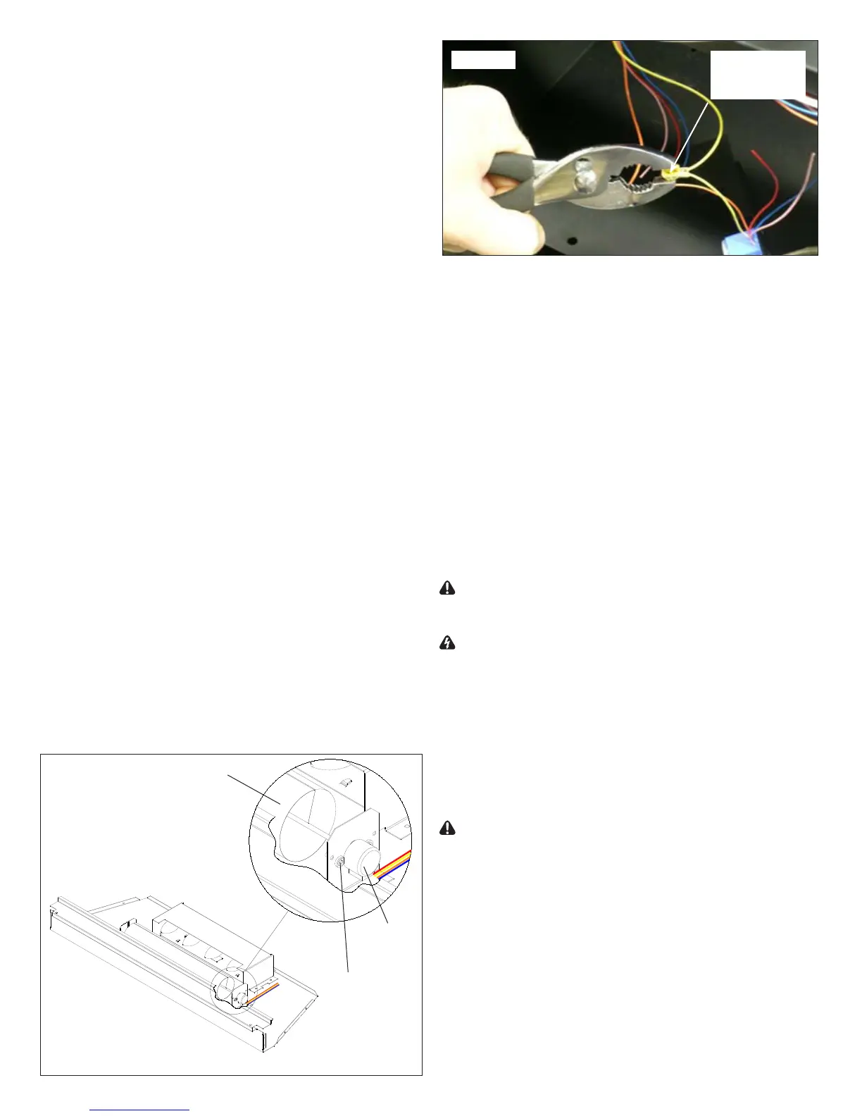
Secure the wire connector by crimping the 3M symbol 14.
with pliers.
Pull on end of wires to ensure a strong connection.15.
Repeat the process for the four (4) remaining wires. 16.
ENSURE THAT ALL WIRES ARE PAIRED BY COLOUR
IN EACH CONNECTOR.
Properly orient and secure the replacement Flicker Motor 17.
to the bracket with screws removed in step 10.
Replace rubber bushing on motor shaft.18.
Replace Flicker Rod.19.
Reassemble rebox in reverse order as above and 20.
replace in mantel.
Remote Controls require no replacement procedure,
however, a re-initialization procedure may need to be
followed. Refer to Page 3 for the Remote Initialization
procedure.
Phillips Head Screwdriver
If unit was operating prior to servicing allow
at least 10 minutes for lights, heating elements and top panel
to cool off to avoid accidental burning of skin.
Disconnect power before attempting any
maintenance to reduce the risk of electric shock or damage
to persons.
Remove the rebox from the mantel.1.
Remove the eight (8) Philips screws that fasten the top 2.
cover to the rest of the rebox. There are: three (3)
screws on each side along the top edge; and two (2)
screws on the back along the top edge (Figure 12).
Flip the top panel over and rest it on the top of the 3.
replace.
Use caution when ipping top panel over as
there are components attached to the top panel which are
wired to the internal cavity of the replace.
Locate the Remote Control Receiver on the right side of 4.
the upturned top panel (Figure 17).
Remove the one (1) white, one (1) orange, one (1) black 5.
wire lead, four (4) cable connectors and the one (1)
white ribbon cable from the Remote Control Receiver as
shown in Figure 17, noting their original locations. The
four (4) cable connectors all use different sized plugs,
reinstallation will not be difcult.
!
The Antenna Wire is permanently attached to the
xed daughter card of the Remote Control Receiver (Figure
17). Do not attempt to remove.
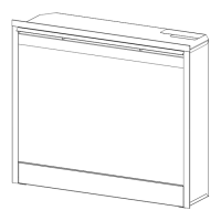
Exploded view used for clarity
Flicker Rod
Flicker
Motor
Screws
(2)
Ensure that all
connectors have
two wires with the
same color