16
Figure 20. Each bracket will be attached to the Heater
Assembly by two (2) Philips screws.
Attach the Cutout to the new Heater Assembly using the 10.
same screw removed in step 8.
Reattach the Heater Assembly to the top panel using the 11.
four (4) screws from step 6.
Using Figure 20 as a reference, as well as notes made 12.
in step 5, reconnect the six (6) wire connections between
the Heater Assembly and Remote Control Receiver.
Reattach the Top Panel to the replace using the eight 13.
(8) screws removed in step 2.
Insert replace back into mantel.14.
Phillips Head Screwdriver
If unit was operating prior to servicing allow
at least 10 minutes for lights, heating elements and top panel
to cool off to avoid accidental burning of skin.
Disconnect power before attempting any
maintenance to reduce the risk of electric shock or damage
to persons.
Remove the rebox from the mantel.1.
Remove the eight (8) Philips screws that fasten the top 2.
cover to the rest of the rebox. There are: three (3)
screws on each side along the top edge; and two (2)
screws on the back along the top edge (Figure 12).
Flip the top panel over and rest it on the top of the 3.
replace.
Use caution when ipping top panel over as
there are components attached to the top panel which are
wired to the internal cavity of the replace.
Disconnect the two (2) wire connections leading from 4.
the existing power cord. One (1) leads to the bottom
terminal of the On/Off Switch, the other leads to the
Neutral terminal on the Remote Control Receiver
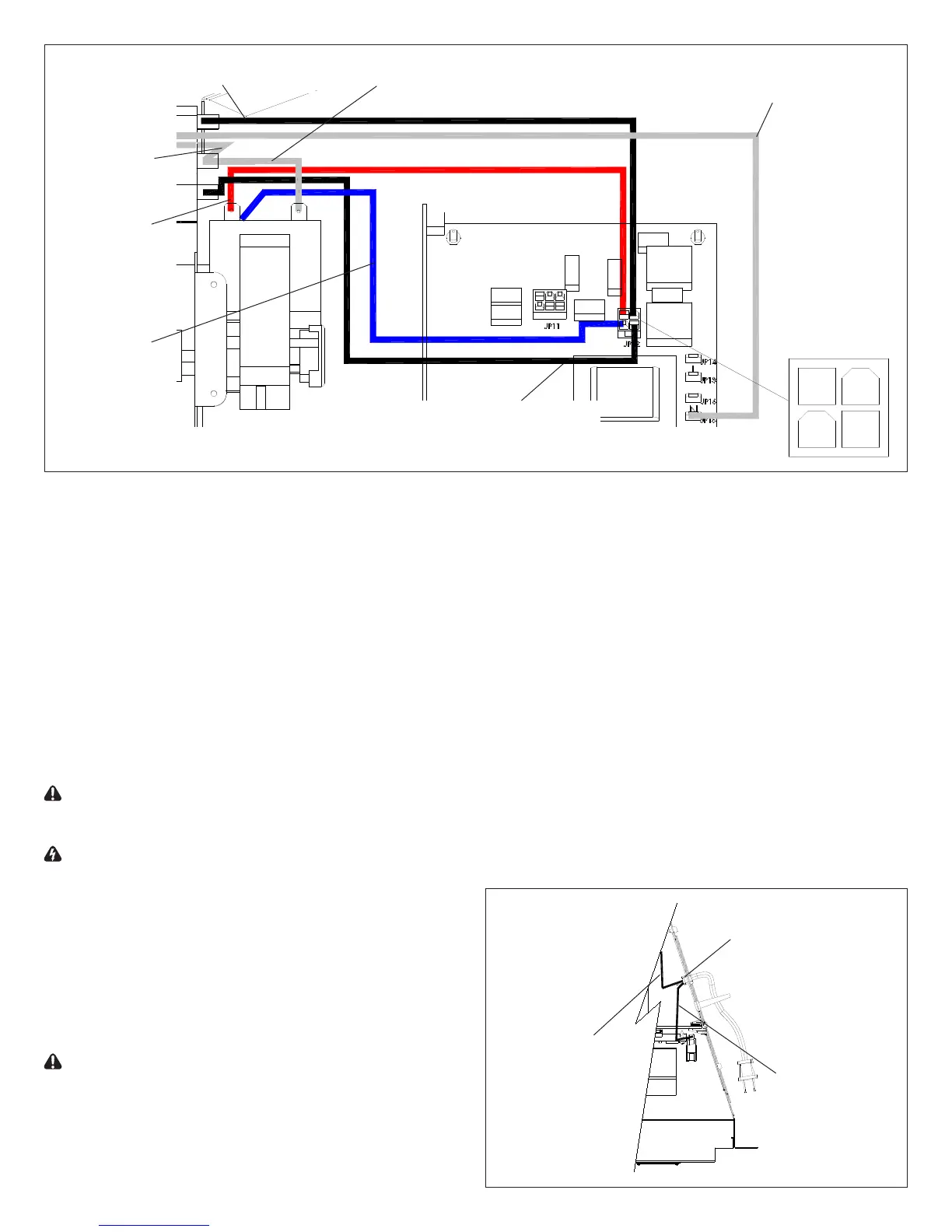
Figure 21
Enlarged view of Heater Assembly and Remote Control Receiver
Long white wire
from Cutout
Black wire from front
terminal of element to P2
White wire looped from right terminal
of motor to upper terminal of element
Red wire from
motor’s upper
left terminal
to P1
Black wire from lower back
terminal of element to P4
P1
P2
P3
P4
Blue wire from
motor’s lower
left terminal
to P3
White wire
from Cutout
to top middle
terminal of
element
Live black wire
from power cord
(smooth side) to
bottom terminal
of On/Off Switch
Neutral black
wire from
power cord
(ribbed side) to
N terminal of
Remote Control
Receiver
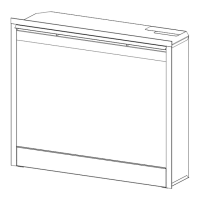
Clamp
mounted to the underside of the Top Panel (Figure 21).
Using pliers, squeeze the sides of the plastic wire clamp 5.
on the inside of the replace and push it, and the power
cord through the chassis (Figure 21).
Release clamp from power cord and remove cord from 6.
replace.
Feed replacement power cord through opening in the 7.
access panel and secure with clamp.
The wide blade of the power plug is designed to be 10.
neutral and is connected to the cord side with ridges in
the rubber of the cord. Connect this side of the Power
Cord to the Neutral (N) terminal of the Remote Control
Receiver.
The other side of the Power Cord will have stamped 11.
writing in the rubber sheath and is live. Connect this side
of the Power Cord to the bottom terminal of the On/Off
Switch.
Reassemble rebox12.
Replace rebox back into mantel and plug in.13.