© 2005 Directed Electronics—all rights reserved
1133
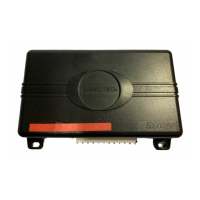
This input comes from the factory set to 2 activation pulses. This means that it is necessary to have 2 consecu-
tive ground pulses on the white/blue wire for the remote start to activate or to deactivate.
NNOOTTEE::
When the activation pulse count can be programmed to 1, 2, or 3 pulses.
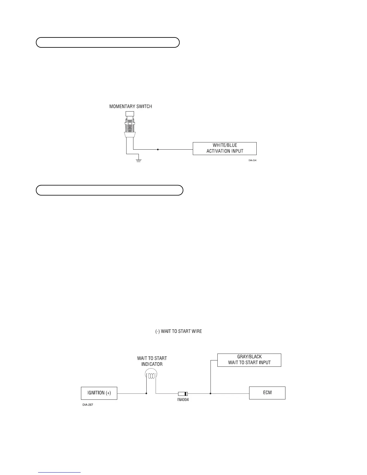
Connect this wire to the wire in the vehicle that sends the signal to turn on the WAIT-TO-START bulb in the dash-
board. In most diesels the wire is negative (ground turns on the bulb) and the GRAY/BLACK can be directly
connected to the wire in the vehicle. If the vehicle uses a positive wire (12V to turn on the bulb) a relay must
be used to change the polarity. (See
Finding the Wires You Need
section for testing procedures.) Here are some
common colors of this wire:
■ Chevrolet and GMC trucks: Light Blue or Dark Blue
■ Ford Trucks: Black/Pink
■ Dodge Ram Trucks: Orange/Black or Black/Orange
NNOOTTEE!!
A 1-amp diode must be installed in line on the factory wire between the wait-to-start indi-
cator and the ECM. (See the following diagram for details.)
HH11//55 GGRRAAYY//BBLLAACCKK ((--)) ddiieesseell wwaaiitt--ttoo--ssttaarrtt bbuullbb iinnppuutt
HH11//44 WWHHIITTEE//BBLLUUEE ((--)) rreemmoottee ssttaarrtt aaccttiivvaattiioonn iinnppuutt
 Loading...