© 2005 Directed Electronics—all rights reserved
1155
IIMMPPOORRTTAANNTT::
Do NOT connect this wire to a negative vehicle light flash wire before changing the
programming jumper to the negative polarity position or damage to the vehicle light circuit may
occur.
As factory configured, the H1/9 WHITE wire should be connected to the (+) parking light wire. If the light flash
polarity jumper is moved to the (-) position (refer to the Programming Jumper section of this guide), this wire
then supplies (-) 200mA output. This is suitable of driving the light control (-) circuits in Toyota, Lexus, BMW
some Mitsubishi, some Mazda, and other models.
NNOOTTEE::
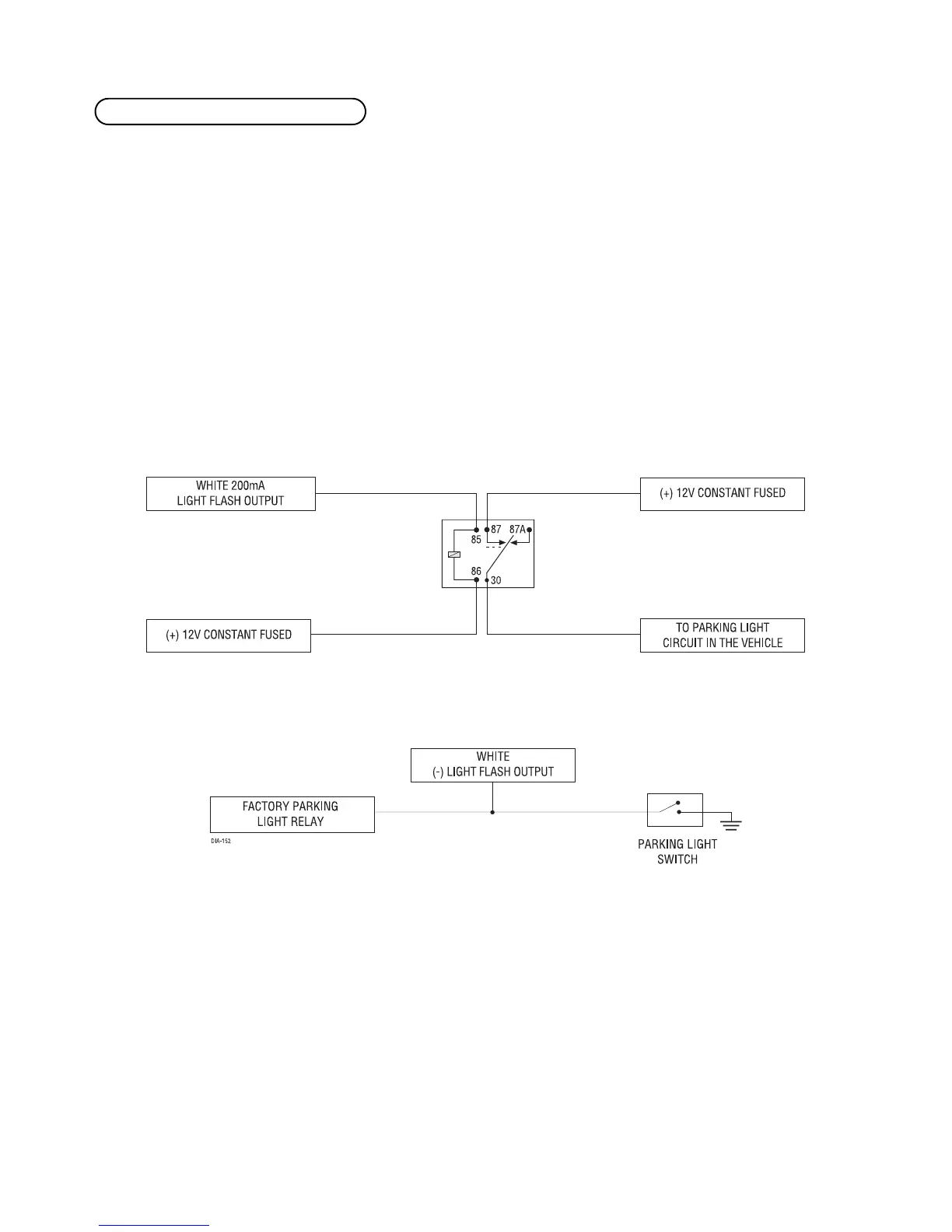
For parking light systems that draw 10 amps or more, the jumper must be placed to the
(-) light flash output (refer to the Programming Jumpers section of this guide. P/N 8617 or a
standard automotive SPDT relay must be used on the H1/2 light flash output wire.
((++)) PPoossiittiivvee LLiigghhtt FFllaasshh OOuuttppuutt
((--)) LLiigghhtt FFllaasshh OOuuttppuutt
HH11//99 WWHHIITTEE ((++//--)) lliigghhtt ffllaasshh oouuttppuutt