12
© 2019 Directed. All rights reserved.
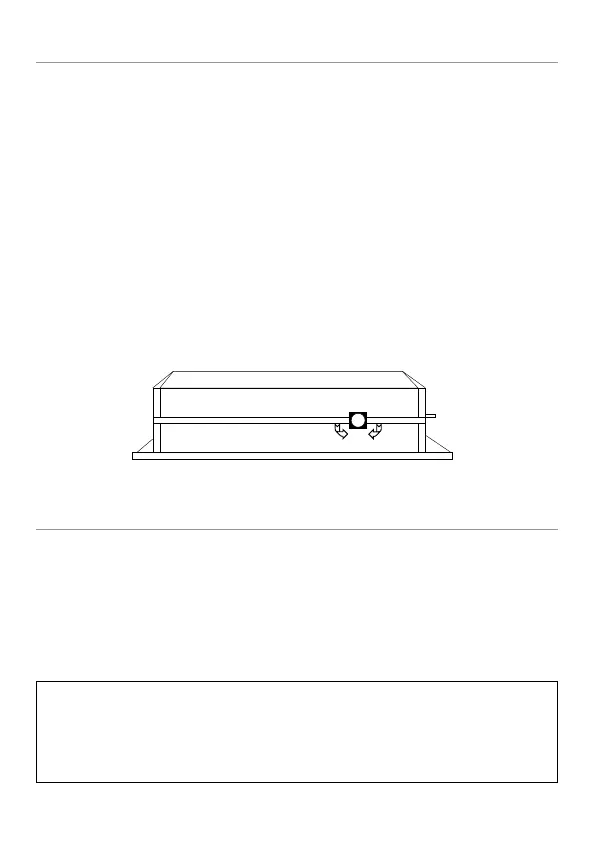
Onboard Dual Stage Shock Sensor
There is a dual-stage shock sensor inside the control unit. Adjustments
are made via the rotary control as indicated in the diagram. The shock
sensor does not work well when mounted firmly to metal, we recom-
mend that you do not screw the control module to metal.
The full trigger of the on-board shock sensor reports Zone 2 (see Table
of Zones section of this guide).
Note: When adjusting the sensor, it must be in the same mounting loca-
tion it will be after the installation is completed. Adjusting the sensor
and then relocating the module requires readjustment.
Optional Sensor Harness, White 4-pin connector
You can add an external sensor using the White 4-pin sensor harness,
as described below, however, this harness is not included with this unit,
and must be ordered separately.
The RED wire supplies constant (+) 12 volts, and the BLACK wire sup-
plies (-) Ground.
Important: The power and ground outputs of this plug cannot support
high current sensors such as a 508D. Power and ground for the sen-
sor should be connected to the red and black wire of the primary
12-pin harness connection.