43
DS4+ FORD6
© 2017-12-13 Directed. All rights reserved.
Type 7
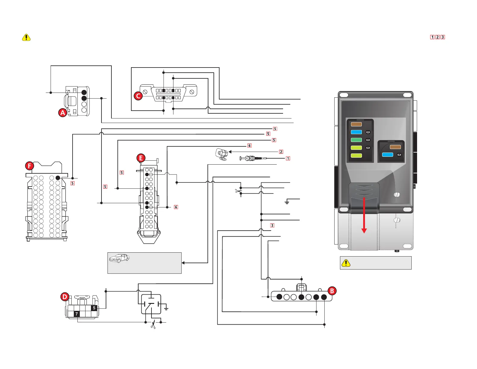
Refer to "Pre-installation and application warnings" on page 4 for important information, such as the description of each special note referenced in the diagram ( ).
16
8
9
1
(-) Ground: Black: 10
MS CAN Low: Tan: 1
(-) Trunk Release Output: Red/White: 4
MS CAN High: Tan/Black: 2
HS CAN High: Orange/Green: 4
HS CAN Low: Orange/Brown: 3
Data RX: Orange/Black: 7
(+) Parking Light Output: White: 5 & 11
HS CAN Low: pin 14
HS CAN High: pin 6
MS CAN Low:
pin 11
MS CAN High:
pin 3
Data TX: Yellow/Black: 8
(-) Lock Output: Dk. Green/Black: 3
(-) Unlock Output: Dk. Blue/Black: 9
(-) Unlock:
Yellow/Red,
pin 5
Driver
Door Trigger:
Lt.Green/Black,
pin2
(-) Lock:
Orange/Black,
pin 8
(+) 12V Input: Red: 6 & 12
P.A.T.S. - 4-pin
(at ignition switch)
1
2
3
4
RX: pin 4
TX: pin 3
DS4+
DS4
Slide
to open
Proper Fuse
Positioning
DS4+ DS4
It is important to check that the
fuses are positioned correctly.
MAIN (5A) (+)
(-) RLY3 PK LIGHT (15A) (+)
(-) ACC & START (30A) (+)
(-) FLEX RLY (20A) (+)
IGN (20A) (+)
MAIN (5A) (+)
(-) RLY3/PK LIGHT(15A) (+)
5
30
20
20
5
15
15
(+) Ignition Input/Ouput: Pink: 10
(+) Accessory Output: Orange: 8
(+) 12V Input: Red/Black: 2
(+) 12V Input: Red: 5
(+) Starter Output (veh. side): Violet: 7
Ignition Switch
(black conn. at ign. switch)
1
2 3 4 5 6 7
14
1
15
16
3
17
4
18
5
19
6
20
7
21
8
22
9
23
10
24
11
25
12
26
13
2
(-) Factory Alarm Disarm Output: Lk. Blue/Black: 10
(-) Factory Alarm
Disarm: Green/Violet or
Lt.Blue/Black, pin 9
Smart Junction Box
(black conn.
passenger kick panel)
(+) 12V:
Lt.Green/Violet, pin 4
(+) Ignition:
White/Yellow,
pin 1
(+) Accessory: Black/Pink, pin 6
(+) Starter: Dk. Green, pin 7
Smart
Junction Box
(black conn.
passenger kick panel)
13
1
26
14
39
27
52
40
RAP Off Interrupt: Lt. Green: 8
RAP Off Interrupt: Lt. Green/White: 9
(-) Trunk
Release:
White/Violet,
pin 13
30
86 85
87
87a
Headlight Switch
Ground:
Black
, pin 7
Cut
(-) Parking
Light:
Black/Lt. Green,
pin 5
Headlight Switch
(gray conn.
headlight switch)
(+) Starter Input (key. side): Green: 6
Cut
Hood
Pin
(-) Hood Pin Input: Gray: 21
Siren
(+) Siren Output: Brown/Red: 11
Refer to the Vehicle wiring
reference charts for wire
and connector details related to the
standard connections in the vehicle.
(AC) Tach Output: Violet/White: 22
OBDII Diagnostic
(connector side view)
 Loading...