56
DS4+ FORD6
© 2017-12-13 Directed. All rights reserved.
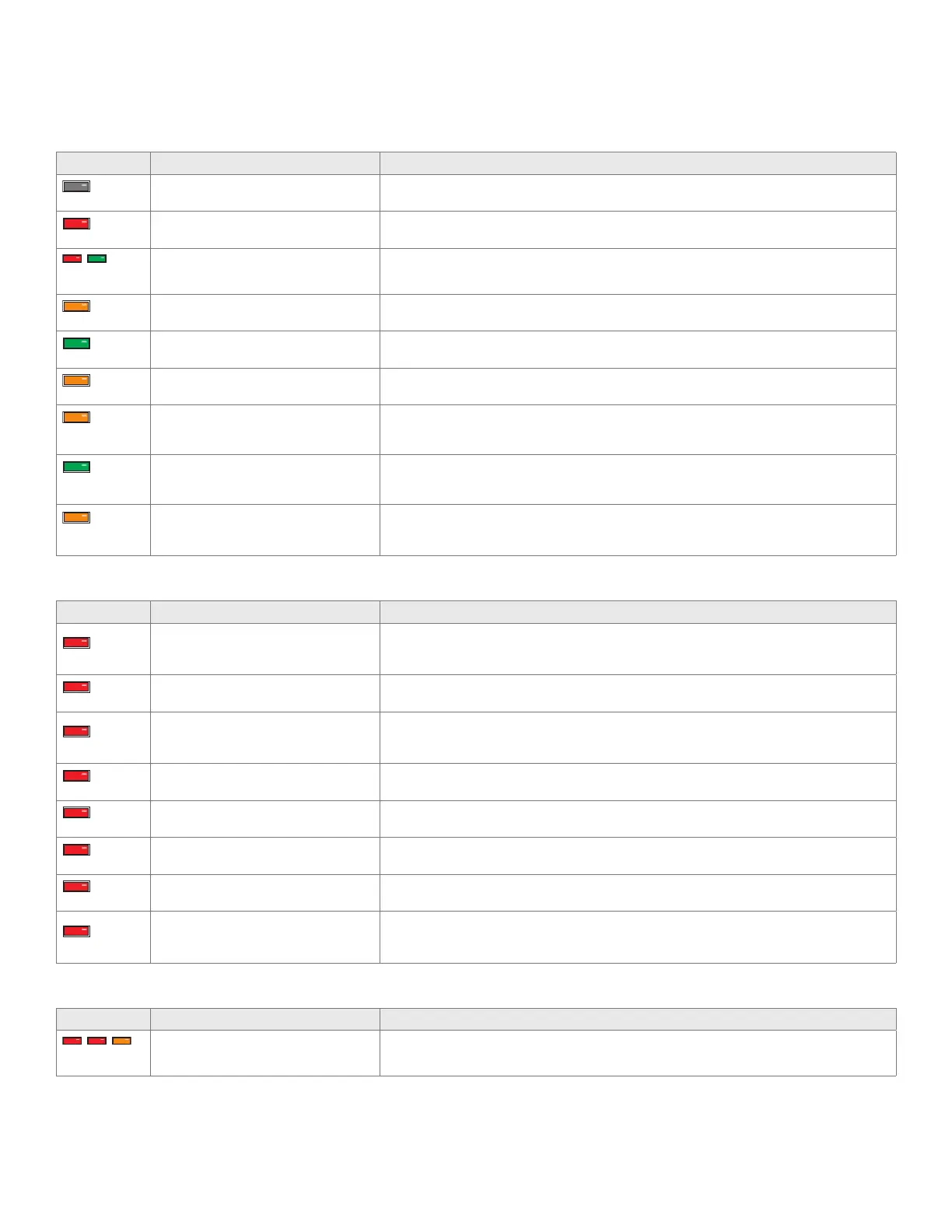
LED diagnostics and troubleshooting
This section provides LED diagnostics and troubleshooting information to guide you through the various stages of your installation.
Module programming
LED Description Troubleshooting
Off
Module has no power.
Make sure the D2D harness is connected and that 12 Volt is present between the red and black
wires. If 12 Volt is present, the module may be defective.
Solid red
Waiting to begin the programming
sequence.
Ensure the correct programming procedure is being followed.
Flashes red &
green
Initialization failed.
Reset the module and complete the programming again. If the issue persists, please contact
Technical Support.
Solid orange
Transponder functions were skipped.
(If compatible) when the RXT mode is not desired or convenience features are needed, please
reset and reprogram the module.
Flashes green
All required CAN networks has been
detected.
Normal operation.
Flashes orange
1 of 2 CAN networks has been detected. Normal operation.
Flashes orange
slowly
Key2GO initiated.
Please follow the steps indicated in "Module programming - 1-Key programming using Key2GO"
on page 55 to complete the Key2GO programming.
Solid green x
3 secs
Module was successfully programmed
with all functions.
Normal operation.
Solid orange x
3 secs
Module was successfully
programmed without transponder
functions.
Normal operation.
Module programming – Error codes
LED Description Troubleshooting
Flashes red x 1
CAN2 not detected.
Check the CAN2 Orange/Green and Orange/Brown wire connections. Wake up the data bus
by turning the ignition on and try again. If your installation does not require this connection, skip
this step by pressing the programming button 5 times.
Flashes red x 1
J1850 not detected.
Check the J1850 wire connection. Wake up the data bus by turning the ignition on and try
again.
Flashes red x 2
CAN1 not detected.
Check the CAN1 Tan and Tan/Black wire connections. Wake up the data bus by turning the
ignition on and try again. If your installation does not require this connection, skip this step by
pressing the programming button 5 times.
Flashes red x 3
Bypass data not detected.
Check the bypass line connection. If more than one wire is used, make sure they are not inverted.
Ensure the vehicle still operates correctly using the factory key.
Flashes red x 4
Bypass processing error.
The bypass calculation failed. Reset the module and try again. If the condition persists, please
contact Technical Support.
Flashes red x 5
ISO 1 not detected.
The Yellow/Black wire did not detect the expected signal. Refer to "Installation (wiring diagrams,
fuse selection & vehicle wiring reference charts)" on page 8 to check the connections.
Flashes red x 6
ISO 2 not detected.
The Orange/Black wire did not detect the expected signal. Refer to "Installation (wiring diagrams,
fuse selection & vehicle wiring reference charts)" on page 8 to check the connections.
Flashes red x 7
MUX not detected.
The Violet/Green or Violet/Brown wire did not detect the expected voltage value. Refer to
"Installation (wiring diagrams, fuse selection & vehicle wiring reference charts)" on page 8 to
check the connections.
External module synchronization
LED Description Troubleshooting
(Flashes red, red,
then orange) x 10
OBDII feature not supported. The diagnostic data bus was not detected, therefore the SmartStart features will be limited.
 Loading...