Do you have a question about the dji ROBOMASTER and is the answer not in the manual?
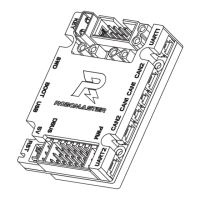
Identifies the main development board unit included in the package.
Visual guide to the board's layout, connectors, and indicators.
Details the power supply circuitry and voltage distribution of the board.
Explains the circuits protecting against reverse connection and overvoltage.
Describes the RGB LED, its control pins, and brightness adjustment.
Details the controllable 5V output port and its connection to the RoboMaster Red Laser Sight.
Explains the BOOT0 and BOOT1 pins for configuring boot methods.
Covers the full-speed USB port for communication and firmware downloads.
Details the SWD port for downloading and debugging programs using emulators.
Describes the RST and KEY buttons and their functions.
Explains the 8-pin connector for IIC/SPI devices and its pinout.
Details the UART ports for serial communication and external conversion needs.
Describes the two CAN ports (2-pin and 4-pin) for ESC control and communication.
Details the seven PWM output ports for servo motors and drive modules.
Explains the DBUS port for remote controller communication and its connection to UART3.
Describes the 18-pin FPC port for DCMI and CMOS camera modules.
Details the SMD passive buzzer driven by PWM for audio output.
Explains the voltage detection circuit for monitoring input voltage VCC_BAT.
Details the integrated BMI088 IMU and its seismic performance and heating circuit.
Describes the IST8310 3-axis magnetometer chip and its IIC communication.
The RoboMaster Development Board Type C is a compact, high-performance STM32 microcontroller-based board designed for use with RoboMaster products and other accessories. It supports a wide range of voltage inputs and offers an expansion interface, communication interface, and high-precision IMU sensors. Key features include anti-reverse connection and anti-overvoltage protection, making it suitable for robotics competitions, research, education, and automation equipment.
The board's power supply includes a 24V to 5V step-down circuit (VCC_5V_M) for seven external PWM servo motor ports, with a maximum total output current of 5A. Another 24V to 5V step-down circuit (VCC_5V) powers onboard devices, providing a maximum output current of 1A. A 5V to 3.3V step-down circuit further supplies power to onboard devices.
An input protection circuit, utilizing an XT30 power input port, prevents reverse connections and ensures slow startup. It also incorporates an overvoltage protection circuit that shuts down the second circuit if the input exceeds 28V.
The board features a customizable RGB LED with common anode configuration, controlled by IO pins PH10 (Blue), PH11 (Green), and PH12 (Red). The LED illuminates when the corresponding IO port's output level is high and turns off when low. Brightness can be adjusted via PWM control.
A controllable 5V port (PC8) allows connection to a RoboMaster Red Laser Sight, with brightness adjustable via PWM.
The BOOT configuration port utilizes the STM32 chip's BOOT0 and BOOT1 pins, determining the boot method after a chip reset. By default, both BOOT pins are low, causing the STM32 to boot from user flash memory. Jumpers can be used to configure BOOT0 and BOOT1 levels, for example, setting BOOT0 to high and BOOT1 to low enables DFU (Device Firmware Update) mode for firmware download via the Micro USB Port.
The Micro USB port is a full-speed USB port that supports USB 2.0 protocol specifications for communication with other devices. In primary mode, it supports full-speed (12 Mbps) and low-speed (1.5 Mbps) transceivers, while in secondary mode, only full-speed (12 Mbps) transceivers are supported. This port can also supply power to the STM32 and some onboard external devices (VCC_5V network only) and is used for firmware download in DFU mode.
A SWD debugging port facilitates program downloading and debugging using emulators like J-Link and ST-Link.
The board includes two buttons: an RST (Reset) button and a customizable KEY button. Pressing the KEY button sets the PA0 pin of the STM32 to a low level.
An 8-pin ejector header connector serves as a customizable I/O port, spaced 2.54mm apart. It can be configured as IIC or SPI ports for connecting communication devices with rated voltages of 3.3V or 5V.
Two UART ports are available: a 4-pin external port for UART1 and a 3-pin external port for UART6 of the STM32. These ports can connect to the RoboMaster Power Management Module, with configurable baud rates. External level conversion chips are required for RS485 or RS232 communication. Both ports support 3.3V and 5V. Note that the silk-screen labels UART1 and UART2 on the board do not correspond to the STM32's serial port configuration; board UART1 corresponds to STM32 UART6, and board UART2 corresponds to STM32 UART1.
Two CAN ports are provided: CAN1 (2-pin) and CAN2 (4-pin). They support a maximum transmission speed of 1 Mbps and can control RoboMaster ESCs or communicate with other devices.
Seven PWM output ports allow connection to 5V servo motor modules or other PWM drive modules.
A DBUS port, sharing a connector with the PWM port, passes the DBUS signal through an inverter circuit to UART3 of the STM32, operating at approximately 100 kbps. DBUS is the general protocol for DJI remote controllers.
An 18-pin FPC port supports DCMI and can connect 8-bit CMOS camera modules, supporting multiple data formats.
A SMD passive buzzer, driven by PWM, has a rated frequency of 4000 Hz. Its output pitch can be adjusted by varying PWM frequencies.
Voltage detection allows monitoring the input voltage VCC_BAT. After division, the voltage connects to ADC (PF10) of the STM32, with a D10 clamp protecting the ADC port.
A 6-axis Inertial Measurement Unit (IMU), specifically a BMI088, is integrated. It offers excellent seismic performance and a damping design for gyroscope reliability. A heating circuit, controlled by TIM10_CH1 (PF6) of the STM32, maintains constant gyroscope temperature to prevent drift. With a 5V heat power and TIM10_CH1 high, the heating power is 0.58W, and the recommended temperature is 15-20°C above the circuit board's normal operating temperature. Communication between STM32 and BMI088 is via SPI, supporting a maximum rate of 10 MHz.
A 3-axis magnetometer chip, IST8310, is integrated. It communicates with the STM32 via IIC, supporting a maximum rate of 400 kHz. The default IIC address is 0x0E.
| Brand | dji |
|---|---|
| Model | ROBOMASTER |
| Category | Motherboard |
| Language | English |